Installation Instructions Discover y ® Range Models: DYRP36DS, DYRP36D-C-S, DYRP48DS, DYRP48D-C-S THIS APPLIANCE HAS BEEN TESTED IN ACCORDANCE WITH THE LATEST EDITIONS OF ANSI Z21.1, UL858 AND UL60730-1, STANDARDS FOR HOUSEHOLD APPLIANCES. Part No. 108106 Rev.
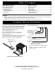
Table of Contents Customer Service Information.....................................................II Important Safety Instructions...................................................... 1 General Safety Precautions......................................................... 2 Planning the Installation............................................................... 3 Electrical Requirements...............................................................3 Product Dimensions.........................................
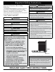
Important Safety Instructions Important Information About Safety Instructions The Important Safety Instructions and warnings in this manual are not meant to cover all possible problems and conditions that can occur. Use common sense and caution when installing, maintaining or operating this or any other appliance. Always contact the Dacor Customer Service Team about problems and conditions that you do not understand.
Important Safety Instructions WARNING • Read the accompanying use and care manual before operating this appliance. • Clean the cooktop thoroughly before operating it for the first time. • Keep packaging materials away from children. Plastic sheets and bags can cause suffocation. • • If you receive a damaged product, immediately contact your dealer or builder. Do not install or use a damaged appliance.
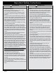
Planning the Installation WARNING IMPORTANT: Observe all governing codes and ordinances during planning and installation. Contact your local building department for further information.
Planning the Installation Gas Supply Requirements • GAS SUPPLY PRESSURE REQUIREMENTS* (All units) The installation of this appliance must conform with local codes or, in the absence of local codes, with the National Fuel Gas Code, ANSI Z223.1/NFPA 54. • Be certain that the appliance being installed is correct for the gas service provided (natural gas or LP gas). Also, if operating the range at an altitude above 4000 ft. (1219 m) make sure it is equipped for high altitude operation.
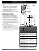
Planning the Installation Product Dimensions Product tolerances: ±1/16” (±1.6 mm) Front of open door Front of handle Front edge of bull nose Front panel Rear of front panel/oven door 48” (121.9 cm) 28 1/2” (72.4 cm) 26 7/8” (68.3 cm) 26” (66.0 cm) 24” (61.0 cm) 1 1/4” (3.2 cm) X* * The optional backguard is available in two heights; 3 and 9 inches high. 1 1/16” (2.7 cm) to cooking surface (top of grates) from top of trim 36 3/16” (91.9 cm) to 37 1/2” (95.
Planning the Installation Cabinet Layout Gas and Electrical Service • All maximum and minimum dimensions and clearances shown in the diagrams below must be maintained for safe operation. • Check the location where the range is to be installed. It should be placed away from drafts that may be caused by doors, windows and heating and air conditioning outlets. • To reduce the risk of fire or personal injury from reaching over a hot appliance, avoid cabinet installations directly above the range.
Installation Instructions Preparing for Installation WARNING • • If the gas or electric service provided does not meet the product specifications, do not proceed with the installation. Call the dealer, the gas supplier or a licensed electrician. Before installing the range, you must locate and secure the anti-tip bracket to the floor. IMPORTANT: Within the Commonwealth of Massachusetts, this appliance must be installed by a licensed plumber or gas fitter.
Installation Instructions Installing the Anti-Tip Bracket on the Floor (cont.) 1. Determine the location of the range center line and front panel for the range’s final position based on the Product Dimensions on page 5 and the actual cabinet/cutout dimensions used for the installation. 2. Determine the required position of the anti-tip bracket, based on the diagram below. Mark the four (4) mounting hole locations on the floor with a pencil. 3. Determine the screw size required.
Installation Instructions Installing the Anti-Tip Bracket on the Wall 1. Determine the suitability of wall mounting the anti-tip bracket. To use the wall mount option, the range front panel must not be more than 26 1/2” (67.3 cm) from the wall and the bracket screws must be able to thread into the base plate inside the wall behind.
Installation Instructions Removing the Oven Door Electrical Connection WARNING • • WARNING Do not attempt to disengage the hinge catches with the door(s) removed from the range. The hinge springs could release causing personal injury. • Wire the range only in compliance with local ordinances. • Improper connection of the electrical wiring can cause an electric shock hazard and damage the appliance. Dacor is not responsible for damages resulting from improper installation.
Installation Instructions Refer to the range rating label (see page II) for power requirements. There are four possible ways to wire the range: • 4 wire conduit • 3 wire conduit (where local codes permit) • 4 wire appliance cord (where local codes permit) • 3 wire appliance cord (where local codes permit) The sections below and on the following pages give directions for connecting each type of wiring harness.
Installation Instructions Electrical Connection (cont.) Connecting the Conduit to the House Electrical Junction Box WARNING Do not connect the green appliance wire to the neutral (white) supply wire unless local building codes permit. NOTES: ◊ 1. The power supply must be properly polarized. Reverse polarity will result in continuous sparking of the burner ignitors, even after flame ignition.
Installation Instructions Separate No. 10 (minimum) copper grounding wire Connection to power supply Junction box Fasten clamp tightly on pipe Wire nut 4 places Connection to appliance (Page 11) 4 Wire Conduit Connection to Junction Box with External Ground No.
Installation Instructions Electrical Connection (cont.) 5. Slide the end of the appliance cord into the strain relief from the bottom of the box. Connecting an Appliance Cord to the Range - Where Local Code Permits 6. Connect the white (neutral) wire to the neutral terminal in the box. 7. Connect the L1 wire to the L1 power supply terminal in the box. 8. Connect the L2 wire to the L2 power supply terminal in the box. 9.
Installation Instructions Gas Connection WARNING Bare wire connections Loop and spade terminal connections L1 terminal • Make sure the gas supply valve is off and that the power to the range is turned off at the circuit breaker or fuse box prior to connecting the gas line. • Do not apply excessive pressure when tightening gas connections and fittings. • Do not use Teflon tape or plumber’s putty on gas flex line connections.
Installation Instructions Final Installation Re-installing the Oven Door(s) 1. Peel the protective coating off of the range, including the door. 2. Measure from the floor to the countertop. Adjust the leveling legs as required to position the trim around the cooktop even with or above the countertop. 3. Locate the anti-tip foot on the back of the range and lower (turn) it until it is 1/16” (2 mm) off the floor.
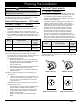
Installation Instructions Installing the Burner Knobs 1. Put the knobs with the words “MAX GRIDDLE” on them A onto the inner (center burner) valve shafts. WARNING Installing the range knobs in the wrong position may result in damage to the griddle included with the range. The knobs for the center burners are marked with the maximum griddle settings. Icons on Center Burner Knobs A NOTE: When installing the knobs, align the “D” shaped opening on the back of the knob with the end of the valve shaft.
Installation Instructions Cooktop Assembly WARNING Never attempt to operate the range’s cooktop with any of the burner rings, burner caps or grates removed. • Remove the burner rings, burner caps and grates from their shipping packages. • Install the burners as shown. Either type (color) of the supplied burner caps may be used. When installing the burner components, twist each piece back and forth slightly until it drops completely into place.
Installation Instructions Verifying Proper Operation Removing the Range for Service Before operating the range, read the accompanying use and care manual completely. It contains Important safety, service and warranty information. 1. Turn the gas supply valve to the off position. 2. 1. Turn off power to the range at the circuit breaker panel or fuse box. 3.
Dacor ● 14425 Clark Avenue, City of Industry, CA 91745 ● Phone: (800) 793-0093 ● Fax: (626) 403-3130 ● www.dacor.