cacor rere a Installation Instructions Epicure® and Millennia® Wall Mount Range Hoods For use with models: EH30, EH36, EH42, EH48, EH54, MH30, MH36 and MH48 APPROVED FOR USE WITH ALL DACOR® RANGES AND COOKTOPS. TESTED IN ACCORDANCE WITH THE LATEST EDITION OF ANSI/UL 507 STANDARD FOR ELECTRIC FANS AND CANI/CSA-C22.2 NO. 113 STANDARD FOR FANS AND VENTILATORS. Part No. 102139 Rev.
Table of Contents Important Safety INStruCtiONS .........cccceeeeeseseseseeereerereeees Important Information About Safety Instructions.............. General Safety Precautions .............c.cccccccccccceeeeeeeeeeenenenes Product Specifications .........cccccccccccecececeeeeeeeeneeseneneeeeeeeees General Specifications ............c.cccceecseseseceesceeeeeeeeeeeeneneeeees DIMENSIONS ........ cece ee eececeecee cece cence eee tececceaecaeeeeeeeeeeetetenneaeas Product Specifications. ..........
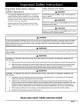
Important Safety Instructions Important Information About Satety Symbols and Labels Safety Instructions + - DANGER The Important Safety Instructions and warnings in Immediate hazards that WILL result-in severe personal these instructions are not meant to cover all possible injury-or-death. problems and conditions that can occur. Use common sense and caution when installing, maintaining or operating this or any other appliance. Always contact the Dacor Customer Service Team WARNING Hazards or.
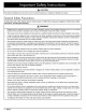
Important Safety Instructions CAUTION For general ventilating use only. Do not-use to exhaust: hazardous or explosive materials and vapors. General Safety Precautions To reduce the risk of fire, electric shock, serious injury or death when precautions, including the following: using your appliance, follow basic safety WARNING Do not install or operate this hood.if it, has. been damaged, dropped, has damaged.electrical wires or-is not-working properly.
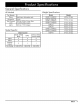
Product Specifications General Specifications All Models Fan Speeds Weight Specifications |4 Filters Exhaust(s) Total Connect Model Mesh type, dishwasher safe EH3012, | 8-inch | 120 Vac, 60 Hz, 9 Amp. Load (10.0 Amp Max. surge) Lights 120 Vac, 75 W halogen Max. 48 lbs. (22 kg) Seer Niaaere 53 Ibs.
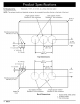
Product Specifications Dimensions Tolerances: +1/16”, -0 (1.6 mm, -0), unless otherwise stated. NOTE: The exhaust duct(s) and electrical wiring can be connected from either the top or the back of the hood. Single exhaust models** Standard 8” duct connection \ oO . Dual exhaust models* Standard 8” duct connection /\ \ Z__| Front of \ yf hood Electrical access holes 7/8” Dia. (5.1 cm) “wn 7 ws XN ome / + | t <> > 1 4 1%” (3.8 cm) ® © \ + N YN \ VW \ Sle ~ 4 v.
Product Specifications OVERALL DIMENSIONS Model A B EH3012 | 29 7/8” (75.9 cm) EH3612 | 35 7/8” (91.1 cm) | 26 7/8” Cc EH4212 | 41 7/8” (106.4 cm) | (68.3 cm) . Overall “ Dimensions EH4812 MH3012 MH3612 MH4812 EH3018 EH3618 EH4218 | | | | | | | 47 29 35 47 29 35 41 7/8” 7/8” 7/8” 7/8” 7/8” 7/8” 7/8” 7 (121.6 (75.9 (91.1 (121.6 (75.9 (91.1 (106.4 cm) cm) cm) cm) cm) cm) cm) EH4818 | 47 7/8” (121.6 cm) . 64.8 am) 5.1m) , at fom) , , ( 4 hom , 26 7/8” (68.3 cm) , EH5418 | 53 7/8 (136.
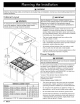
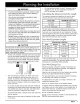
Planning the Installation WARNING Observe all governing codes and ordinances during planning and installation. Contact-your local building department-for further information. Cabinet Layout IMPORTANT See the diagram for minimum installed distance from the hood. to the cooktop surface. The minimum specified distance may.be higher for the particular range-or cooktop in use. Check the manufacturers specifications for the cooktop or range.
Planning the Installation WARNING * On dual exhaust models, the two 8” exhausts may be merged into one 10” duct using Dacor transition kit AHT10. See page 16 for details. «To. prevent-combustion by-products, smoke or odors from entering the home and to improve efficiency, tape all duct joints securely. Calculating the Maximum Duct Run Length «- The maximum straight duct length for the hood is determined by the type of duct used. See the chart below. Use only.
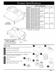
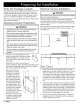
Preparing for Installation Verify the Package Contents Electrical Service Installation Unpack the parts box and verify that all parts have been included according to the parts list on page 5. If any item is missing or damaged, please contact the dealer immediately. Do not install a damaged or incomplete appliance. Make sure you have everything necessary for proper installation before proceeding. Mounting Location Preparation WARNING WARNING The electric service to the range.
Preparing for Installation SX J Back wall Ceiling or cabinet ‘] bottom DNaS: S ° a) AS aes é Duct Cut-Out for Rear Venting Duct Cut-Out for Top Venting Installation Instructions WARNING + Blower Rotation Instructions Do not install the range hood unless the electrical MODEL service provided meets the range hood specifications. EH3012, EH4212 MH3012, FH4812, MH4812 «Observe all governing codes and ordinances during SEE PAGE EH3612, MH3612, 10 11 installation.
Installation Instructions Rotating the Blower for Models: 8. Disconnect the wiring harness connector from the blower motor. EH3012, MH3012, EH3612, MH3612 and EH4212 (Models that are 12 inches high equipped with a single blower) 9. While supporting the blower from below, remove the four (4) nuts that hold the blower and mounting plate in place. Remove the blower from the hood. 1. Place the hood assembly on a large flat surface. 2.
Installation 13. Insert the opening the hole inside the on the motor must Attach it using four on the blower motor assembly into back of the hood. The connector be toward the bottom of the hood. (4) nuts. Instructions 17. Tip the hood back down so that the top of the hood faces up. Using existing screws, attach the cover plate removed in step 3 to the top of the hood to cover the hole. so eo en fl ‘ , 18. Attach the duct collar removed in step 2 to the back of the unit using four (4) existing screws.
Installation Instructions 4. Tip the hood back, so that it lays on its back with the front pointing up. 10. Remove and discard the mounting plates Remove the filters from the under side of the hood. Locate the wiring harness. Cut the cable tie that takes up the slack in the cable. It is located behind the panel on the right side inside the hood. Also cut the two (2) cable ties that hold the wiring harness to the brace inside the hood, on the right side. See below. 7.
Installation 14. Route the wiring harness as shown below. Secure the harness to the motor assemblies using the cable clamps supplied with the hood in the positions shown. 15. Attach the wiring harness to the brace inside the hood, on the right side using two (2) supplied cable ties. 16. Use a cable tie to take up any remaining slack that may exist in the wiring harness. Stow the harness behind the plate on the right side. Securing any slack will reduce additional noise due to vibration.
Installation Instructions 8. Disconnect the wiring harness connector from the blower motor. 9. While supporting the blower from below, remove the four (4) nuts that hold the blower in place. Remove the blower from the hood. 11. Route the wiring harness as shown. Secure the harness to the motor assembly with the cable clamps supplied with the hood in the positions shown below. 12. Attach the wiring harness to the brace inside the hood on the right side using two (2) supplied cable ties. 13.
Installation Instructions Rotating the Blower for Models: 8. Disconnect both wiring harness connectors from the blower motors. EH4818, MH4818 and EH5418 (Models that are 18 inches high equipped with two blowers. 9. While supporting each blower from below, remove the four (4) nuts that hold each blower in place. Remove both blowers from the hood. 1. Place the hood assembly on a large flat surface. 2. Remove and save the screws and the two (2) duct collars from the top of the unit. 3.
Installation Instructions 11. Route the wiring harness as shown. Secure the harness to the motor assemblies using the cable clamps supplied with the hood in the positions shown below. 12. Attach the wiring harness to the brace inside the hood, on the right side using two (2) supplied cable ties. 13. Use a cable tie to take up any remaining slack that may exist in the wiring harness. Stow the harness behind the plate on the right side. Securing any slack will reduce additional noise due to vibration.
Installation 12” high models with rear exhaust: Instructions 3. Center the transition over the duct collars while resting the unmodified edge on the top of the hood. Fasten in place using sheet metal screws (not included). Seal the base of of the transition with duct tape. Find the temporary mounting bracket in the shipping box. Put the bracket against the wall and line up the center hole with the intersection of the bracket center lines on the wail.
Installation Instructions Hanging the Range Hood Duct Work Installation WARNING WARNING Hanging the range hood requires two people..Do not attempt to lift the hood without assistance. 1. Remove the plastic coating from the outside of the hood. 2. Remove the filter(s) to reduce weight and avoid damage. 3. Lift the hood up on both sides and slip the mounting slots over the tabs on the mounting brackets. 4.
Installation Instructions Final Electrical Installation WARNING «To avoid-electric shock or fire hazard, prior to-connecting the electrical wiring to the hood, make sure.that power-to the hood. power supply line is turned off at-the fuse box or circuit breaker panel. «Improper connection of the hood electrical wiring may.create an electric shock or fire hazard and:may result in damage to the hood’s electrical system. See page.6 for:specifications. «.-.
Installation Instructions WARNING «-...Do not ground the circuit to a gas line. «Do not-ground the circuit to.a hot water-pipe. «Water lines. that-are-insulated must be.jumped to assure.continuity to ground. See. below. To house circuit breaker panel or fuse box \u Separate No. 10 (minimum) copper ground wire WHITE Fasten clamp tightly on pipe UU Wire nut, 3 places J “NN UL/CSA approved . : NEMA strain relief Junction No.
Installation Instructions Verifying Proper Operation CP WARNING Main power Feature keys \ Installation Checklist switch \ SS| tp i ) ZO ZL Filters ——% e.-Jo ensure.a safe and proper:installation, the following checklist-should be completed by the installer to ensure that no part of the installation has been overlooked. «Proper installation is. the responsibility of the homeowner. The importance of proper installation of your Dacor range:hood cannot-be overemphasized.
HOOD LIGHTS 75W, 120V EACH VY) y [er iolpey = jwiw fi09 8765432 re} K4 K3 K2 1/P2 K1 = rt HOOD (a POWER AND CONTROL BOARD MICROPROCESSOR B HEADER | ° PROGRAMMING Cc — WIRE W B Y O COLOR 2 4 68 10 1357 9 |P3 [10987654321 CODE errr - WHITE - BLUE - YELLOW - ORANGE CHASSIS GROUND Ww lo R- RED BL- BLUE BR - BROWN G - GREEN V - VIOLET ]P2 tp oF R 9Oo} or B ° Gecar i— eacer HOOD KEYPAD MEMBRANE W CONNECT TO g ~ CHASSIS GROUND Wiring Diagram - Single Blower Models
HOOD LIGHT 75W, 120V YT] HOOD LIGHT 75W, 120V w yy] Y |B HOOD LIGHT 75W, 120V w YT WR joje Bl K3 K2 zs=; jwiw 1098765432 K4 w 1]P2 K1 HOOD POWER AND CONTROL BOARD BLOWER 455W, 115V BLOWER 455W, 115V POWER SWITCH MICROPROCESSOR BI HEADER] 8 PROGRAMMING 2 4 68 10 1357 9 “ip |P3 [v7 10987654321 WIRE COLOR CODE W- WHITE B- BLUE Y - YELLOW O - ORANGE R - RED BL - BLUE BR - BROWN G- GREEN V - VIOLET z OOOO @®|© |_O] aeser = CHASSIS GROUND 4Aos2ep CHASSIS GROUND =| ” HOOD KE
24 dacor.
dacor. Family Owned The Life of the Kitchen? Dacor e 600 Anton Bivd. Suite 1000 Costa Mesa, CA 92626 « Phone: (800) 793-0093 American Made e Fax: (626) 403-3130 « www.Dacor.