
Specifications


Page 7
NOTES:
1. No adjustment of burner settings is required. All valves and air mixture shutters found in this
appliance have been factory preset.
2. Liquid propane (LP) grills should be special ordered from the factory. Liquid propane units are
identified by the “LP” designation at the end of the model number on the product identification
chassis tag.
3. Under extenuating circumstances, outdoor grills may be field converted to operate on LP gas
or at elevations in excess of 5,000 feet above sea level. However, field conversion must be
completed by a qualified service agency and authorization must be granted by the factory prior
to any field conversion.
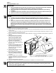
4. To prevent damage to the gas regulator, install the regulator only after the grill is mounted in
its permanent position in the enclosure or cart. Ensure the arrow on the regulator points in the
direction of the gas flow towards the grill.
STEP 3
Gas and Electrical Supply Requirements
WARNINGS:
1. The maximum gas supply pressure to the regulator must not exceed 1/2 pound per square inch.
2. Verify proper gas supply has been provided. Refer to Table 1.
3. Do not apply excessive pressure when tightening connections and fittings.
4. Do not use plumber’s putty or Teflon tape on gas compression connections. It can defeat the
proper sealing of these fittings. Use plumber’s putty or Teflon tape only on pipe thread fittings.
5. Turn all outdoor grill control valves to the “OFF” position, then turn on the gas supply. Check
all supply lines and connections for leaks using a soap and water solution. Do not use a flame
to check leaks. After verifying that there are no gas leaks, turn off the gas supply to the grill
by turning the gas shut-off valve to the “OFF” position. Leak testing of the appliance shall be
conducted according to the manufacturer’s instructions.
6. For LP cylinder installations, the LP gas cylinder must have its own Certified high-pressure
regulator (Either Type I or No. 600 Connection).
7. Natural gas installations will be connected to factory supplied natural gas regulator. Refer to
Natural gas connections in this manual for details.
8. Inspect the gas line before and after installation. Also, inspect the line for damage before each
use of the outdoor grill.
STEP 4
Gas Connections
Natural Gas Connections
Verify gas supply pressures are acceptable based on Table Number 1, on page 6.
The Dacor outdoor cooking products ship with a 3/4 inch nipple, regulator, and 1/2” reducer for gas supply connections.
Install a 3/4 inch (19mm) or 1/2 inch (13mm) natural gas supply line, with a shut off valve (not included with the outdoor product), in an
accessible location under the appliance. Place the gas supply line and shut off valve inside the base enclosure within a reachable distance
from the front access doors or open rear area of the enclosure. Refer to base enclosure planning and cutout dimensions page within this
manual for additional detail.
.
Connect the, factory supplied, regulator and gas line nipple at the back right bottom corner of the grill. Use only approved gas line thread
compound, regulators, and gas hose. Be certain the gas flow arrow on the regulator is installed with the flow in the correct direction.
Install approved flexible gas line from the regulator to the rough gas line shut off valve using the factory supplied regulator.
Check all gas connections for leaking by applying a water and soap solution. If you observe leakage (soap bubbles around any connections)
do not attempt to operate the grill without correcting the leak.