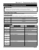
SECTION 7 - TROUBLESHOOTING GUIDE Section 7 - Troubleshooting Guide IMPORTANT • While this troubleshooting guide provides information to aid in troubleshooting problems with the range, it does not contain information on every possible type of failure. • See Appendix A to determine when elements and convection fan should be on or off. Control Panel Error Codes The error codes below apply to both models ER36D and ER48D.
DACOR RANGE SERVICE MANUAL Basic Troubleshooting Instructions 1. If the range does not function properly, check for obvious problems first, such as the main power switch being turned off, or the control panel being locked. 2. If the problem is not immediately obvious, use the Performance Tests in Appendix B and consult the Troubleshooting Chart on the following pages to help locate the problem.
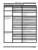
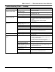
SECTION 7 - TROUBLESHOOTING GUIDE Troubleshooting Chart - Oven (continued) PROBLEM Time on display not correct. Time flashes on display. Oven does not selfclean. Display is lit. Oven controller beeps when keys are pressed. Cooktop works OK. Oven lights will not work. Oven heats normally and cooktop works OK. POSSIBLE CAUSES WHAT TO CHECK Time of day not set. • Set time. Power failure or power was turned off. • Reset time. Control panel problems. • Oven controller board.
DACOR RANGE SERVICE MANUAL Troubleshooting Chart - Oven (continued) PROBLEM POSSIBLE CAUSES Foods over or under cook. Incorrect cooking time or temperature. WHAT TO CHECK • Follow instructions in Operating Instructions section. Items not being cooked on rack level that will provide best results. • See Understanding the Various Cooking Modes section. Food placed in oven during pre-heat. • Make sure pre-heat indicator on display is off before putting food in oven (does not apply to broil modes).
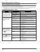
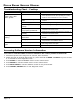
SECTION 7 - TROUBLESHOOTING GUIDE Troubleshooting Chart - Cooktop PROBLEM Igniters do not spark. Control panel is dark. POSSIBLE CAUSES WHAT TO CHECK Range not connected to electrical power. • Have electrician connect range to properly wired electrical connection. Power to range is off. • Turn power on at junction box. Check for tripped circuit breaker or blown fuse. Power outage. • Contact power company. Igniters do not spark. Control panel is lit. Wet or dirty igniter.
DACOR RANGE SERVICE MANUAL Troubleshooting Chart - Cooktop PROBLEM Igniter continues to spark (click) after flame ignites. Flame goes out at low setting. Burner knob does not light. POSSIBLE CAUSES WHAT TO CHECK Burner is cold. • Burners may continue to spark for up to 60 seconds when cold and set to low. See Operating the Cooktop section for more information on how to minimize. Flame distorted by air draft. • Minimize any air drafts around the range. Close nearby windows. Wet or dirty igniter.
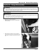
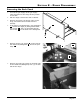
SECTION 8 - RANGE DISASSEMBLY Section 8 - Range Disassembly DANGER • Turn off electrical power at the main power supply and the gas supply at the gas supply valve before servicing the range. Failure to turn off electrical power and the gas supply to the range will result in a electric shock and explosion hazard. Door Removal WARNING • Do not attempt to disengage the hinge locks on the door while it is removed from the oven. The hinge springs could release, causing personal injury.
DACOR RANGE SERVICE MANUAL Door Installation WARNING • Be sure that the notch on the bottom of each hinge rests on top of the lower lip of each hinge receptacle before attempting to open the oven door. Failure to do so may cause the door to fall off its hinges, resulting in personal injury or damage to the door. • Rotate the hinge locks toward the front of the range immediately after installation of the door.
SECTION 8 - RANGE DISASSEMBLY Removing the Back Panel • Turn off the gas supply at the gas supply valve and power to the range at the junction or fuse box. • Pull the range out from the wall or cabinet. • Remove the grates, the burner caps, burner rings, and crown burner heads from the cooktop. • If the range is equipped with a 24” backguard F , remove the eight (8) backguard bracket hex screws G . They are accessed through the 8 holes H on the back of the backguard.
DACOR RANGE SERVICE MANUAL Removing the Back Panel (continued) • Pull the island trim/backguard J up and off the range. • Remove the stainless steel spill tray trim piece L. J L • Remove the electrical access panel cover N by removing the two (2) screws M that hold it in place. • Remove the two (2) screws O on the sides of the electrical access panel. It is not necessary to remove the gas regulator access panel cover P .
SECTION 8 - RANGE DISASSEMBLY Removing the Side Panel(s) • Turn off the gas supply at the supply valve and power to the range at the junction or fuse box. • Pull the range out from the wall or cabinet • Remove all of the screws from the edge of the back panel A on the same side of the range as the side panel being removed. • Loosen the end cap set screws B through the access holes C on the bottom of the front panel lip D . A B D C • Remove the end cap.
DACOR RANGE SERVICE MANUAL Removing the Side Panel(s) (continued) • Remove the side panel screw inside the front panel lip. • Remove the grates, the burner caps, burner rings, and crown burner heads from the cooktop. • Remove the screws above the spill tray that hold the side panel in place. • Lift the side panel off of the range.
SECTION 8 - RANGE DISASSEMBLY Removing the Spill Trays CAUTION • Take care when disassembling the spill tray. Many of the spill tray components are porcelain coated and can chip. E • Turn off the gas supply at the supply valve and power to the range at the junction or fuse box. • Remove the grates, the burner caps, burner rings, and crown burner heads from the cooktop. • Remove the spill tray trim screws, located above the spill trays E , from the back, front, and side panels.
DACOR RANGE SERVICE MANUAL Removing the Spill Trays (continued) • Remove the screws from the stack burner heads H (eight [8] screws total). H • Remove each of the stack burner heads. When removing the head, disconnect the igniter wire from each one. • Gently lift up on the back of one of the porcelain trim pieces I where the spill trays J come together. Pull it toward the back of the range and out of the stainless steel trim piece above the front of the spill tray.
SECTION 9 - COMPONENT REPAIR Section 9 - Component Repair DANGER • Turn off electrical power at the main power supply and the gas supply at the supply valve before servicing the range. Failure to turn off electrical power and the gas supply to the range will result in a electric shock and explosion hazard. Door Component Repair WARNING • Do not attempt to disengage the hinge locks on the door while it is removed from the oven. The hinge springs could release, causing personal injury.
DACOR RANGE SERVICE MANUAL Door Handle (ER36D) • Remove the oven door. See the Door Removal section on page 8-1. • Lay the door on a flat, padded surface with the door gasket facing up. • Remove the two (2) door handle screw plugs X . The door handle mounting screws are located below the plugs. • Remove the two (2) door handle screws Y . Do not remove the door liner screws B . • Grasp the door with one hand and pull up. Pull the door handle out from underneath.
SECTION 9 - COMPONENT REPAIR Door Component Repair (continued) Front Door Glass Assembly B B WARNING • To prevent personal injury, use gloves when handling glass components that are broken or shattered. • Remove the oven door. See the Door Removal section on page 8-1. • Lay the door, handle down, on a flat, padded surface with the door gasket facing up. • Remove the two (2) screws B in the top corners of the door. • On ER48D Only: Grasp the top end of the door with one hand and pull up.
DACOR RANGE SERVICE MANUAL Door Component Repair (continued) • When putting the front door glass assembly back in place, be careful not to knock loose the door spacers which are glued to the top corners. Also, make sure the tabs E on the bottom rest on the outside of the door liner. • Reinstall the screws on the bottom of the door, then grasp the top of the door with both hands and turn it over. • On ER48D Only y: Hold the top end of the door up with one hand.
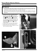
SECTION 9 - COMPONENT REPAIR Door Hinges (continued) • Grab the front door glass assembly with both hands and remove it. • Remove the two (2) hinge cover screws F over the hinge to be removed and pull off the hinge cover G . • Remove the hinge retainer screw H for the hinge to be removed. G G F F F F H H • Carefully pry up the hinge I up and out of the door. • After installing the hinge, replace the hinge cover and the three (3) screws that hold the hinge assembly in place.
DACOR RANGE SERVICE MANUAL Door Component Repair (continued) Inner Window Assembly B B WARNING • To prevent personal injury, use gloves when handling glass components that are broken or shattered. • Remove the oven door. See the Door Removal section on page 8-1. • Lay the door, handle down, on a flat, padded surface with the door gasket facing up. • Remove the two (2) screws B in the top corners of the door. • On ER48D only: Grasp the top end of the door with one hand and pull up.
SECTION 9 - COMPONENT REPAIR Inner Window Assembly (continued) • Remove the four (4) screws J that hold the outer heat shield K in place. Lift the outer heat shield out. K J J J J • Remove the four (4) screws L that hold the lower outer heat shield M in place. Lift the lower heat shield out. M L L L L • Remove the four (4) screws N that hold the inner heat shield O in place. Lift the inner heat shield up and out toward the top of the door.
DACOR RANGE SERVICE MANUAL Door Component Repair (continued) • If the inner widow gasket P must be removed, make sure it is fit completely into the groove around the window opening before replacing the window assembly. • Replace the window glass assembly. The seam in the metal rim around the inside of the glass must be placed toward the top of the door. • Replace the inner heat shield and tighten into place using the existing screws.
SECTION 9 - COMPONENT REPAIR Cooktop Component Repair General To make repairs to the cooktop gas supply lines (flex tubes), remove the spill trays. See page 8-7 for instructions. Each burner is fed by two (2) flex tubes from the valve. The larger flex tube is the main gas supply line. It supplies gas to the main orifice on each burner. The smaller flex tube is the simmer line. It supplies gas to the simmer orifice on each burner assembly.
DACOR RANGE SERVICE MANUAL Cooktop Component Repair (continued) Regulator • Turn off the gas supply at the supply valve and power to the range at the junction or fuse box. • Pull the range out from the wall or cabinet. • Remove the gas regulator access cover A from the back of the range B . • Disconnect the gas supply line C to the regulator D . • Disconnect the flex tube E from the top of the regulator.
SECTION 9 - COMPONENT REPAIR Cooktop Component Repair (continued) Igniters and Orifices (injectors) Replacement of the crown burner igniters or orifices require the removal of the spill trays. The spill trays do not need to be removed to replace the stack burner igniters or orifices. Stack Burner • Turn off the gas supply at the supply valve and power to the range at the junction or fuse box. • Remove the grates. • Remove the burner ring and burner cap from the stack burner.
DACOR RANGE SERVICE MANUAL Cooktop Component Repair (continued) Stack burner orifice replacement • Use a 7 mm hex driver or socket to remove the orifice from the burner base. The main orifice M is located in the center of the burner. The simmer orifice N is located near the outside of the base. Consult the Dacor technical service department for the correct orifice size. The size of each orifice is stamped on its side. • Tighten the replacement orifice into place with the 7 mm hex tool.
SECTION 9 - COMPONENT REPAIR Crown burner orifice replacement (continued) • The simmer orifice is attached to a fitting on the side of the crown burner. Remove the fitting retaining clip T to access the simmer orifice fitting. • Pull the fitting U out of the side of the burner. • Use a 7 mm hex wrench to remove the simmer orifice V from the fitting. • Tighten the replacement orifice into place with a 7 mm hex wrench. • Repeat the above steps for the other crown burner if it requires service.
DACOR RANGE SERVICE MANUAL Cooktop Component Repair (continued) Igniter Module • Turn off the gas supply and power to the range at the junction or fuse box. • Remove the spill trays. See the Removing the Spill Trays section on page 8-7. • Determine the igniter to be replaced by tracing the igniter wire G from the burner that is not sparking back to the module H . The igniter modules are located under the igniter module insulation I .
SECTION 9 - COMPONENT REPAIR Cooktop Component Repair (continued) Manifolds and Valves • Turn off the gas supply and power to the range at the junction or fuse box. • Remove the spill trays. See the Removing the Spill Trays section on page 8-7. • Remove the torx head screws from the end caps F through the access holes G on the bottom of the front panel lip H . • Remove the end cap. • Pull the all the knobs off the front of the range. • Remove the side panel screw inside the front panel lip.
DACOR RANGE SERVICE MANUAL Cooktop Component Repair (continued) • Make sure the oven control panel I is in the lowered position. See page 5-2. • Pull the bottom of the front panel J out and lift it up and off the range. I J • Remove all of the screws that hold the channel support K to the cooktop chassis. Lift the channel support out of the chassis. • Disconnect the wires L from the valves connected to the manifold M to be removed.
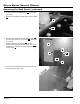
SECTION 9 - COMPONENT REPAIR Manifolds and Valves (continued) • • To remove the valves P , remove the bolts Q from the bottom of the manifold R . P After repairs are completed, reassemble the cooktop and test it to make sure repairs were properly completed. R Q Oven Component Repair Smoke Eliminator • Turn off the gas supply at the supply valve and power to the range at the junction or fuse box. • Remove the oven door as described on page 8-1. • Remove the oven racks.
DACOR RANGE SERVICE MANUAL Oven Component Repair (continued) The oven chamber smoke eliminator D is located on the ceiling of the oven chamber near the back. Exact location varies with model. • Remove the three (3) screws that hold the smoke eliminator in place. Be careful not to scratch the back of the oven with the screwdriver during removal and installation. • To install the smoke eliminator, fasten it in place with the three (3) existing screws. • Reinstall the broil element if necessary.
SECTION 9 - COMPONENT REPAIR Oven Component Repair (continued) Convection Element, Fan and Fan Motor • Turn off the gas supply and power to the range at the junction or fuse box. • Remove the oven racks from the oven. • Remove the oven door(s) as described on page 8-1. • Remove the convection filter from the back wall of the oven by lifting it up and out. Q Convection Baffle Removal • Remove the four (4) screws that hold the convection baffle P in place.
DACOR RANGE SERVICE MANUAL Oven Component Repair (continued) Convection Fan and Fan Motor Removal • To remove the convection fan U , hold it with one hand and turn the nut V clockwise with a wrench. • With the back cover removed (see page 8-3), label the location of the convection fan wires W and disconnect them. • Remove the three (3) screws X that attach the motor Y to the back panel to remove it • Reassemble the fan motor and fan in the reverse order.
SECTION 9 - COMPONENT REPAIR Oven Component Repair (continued) Broil Element Left oven on Model ER48D: • Turn off the gas supply at the supply valve and power to the range at the junction or fuse box. • Remove the oven door as described on page 8-1. • Remove the oven racks. • Remove the convection filter E from the back wall of the oven by lifting it up and out. • Remove the four (4) screws that hold the convection baffle A to the back of the oven and remove it.
DACOR RANGE SERVICE MANUAL Oven Component Repair (continued) • Label the wires G that connect to the broil element terminal. • Gently remove the broil element wires from the terminal block H on the broil element assembly. G H • Place the broil element assembly on a flat, padded surface and remove the screws from each of the four (4) corners. • The broil element assembly separates into three (3) components, the broil element I , the broil element frame J , and the broil element glass K .
SECTION 9 - COMPONENT REPAIR Broil Element (continued) • Place the broil element into the oven chamber with the glass facing down and the terminals toward the back of the oven. • Lift the back of the element up and reconnect the broil element wires to the terminals on the broil element assembly. Make sure that the wires are connected to the proper terminals. • Insert the broil element assembly into the hole in the oven ceiling while pushing the broil element wires into the access hole toward the back.
DACOR RANGE SERVICE MANUAL Oven Component Repair (continued) Broil element for right oven on Model ER48D and oven on Model ER36D: • Turn off the gas supply at the supply valve and power to the range at the junction or fuse box. • Remove the oven door as described on page 8-1. • Remove the oven racks. • Remove the screws that hold the bake element frame D in place on the floor of the oven. • Remove the bake element frame and glass E .
SECTION 9 - COMPONENT REPAIR Oven Component Repair (continued) Temperature Sensor and Rack Support The following applies to all ER36D and ER48D ovens, including the left oven on model ER48D: • Turn off the gas supply at the supply valve and power to the range at the junction or fuse box. • Remove the oven door as described on page 8-1. • Remove the oven racks from the oven chamber. • Remove the four (4) screws that hold the right rack support H in place.
DACOR RANGE SERVICE MANUAL Oven Component Repair (continued) Reinstalling the Rack Support: CAUTION • To prevent damage to the oven wall, insert the rack support carefully. • Insert one end of the rack support into the oven at a 20° angle to the sidewall. • Rotate the rack support into place, matching the four (4) protruding pins on the rack support to the holes in the oven wall. • Mount the rack support in place using the four (4) existing screws.
SECTION 9 - COMPONENT REPAIR Oven Component Repair (continued) Light Fixtures and Meat Probe (continued) • • Remove all the mounting screws from the intake grill K . The screws attach the grill to the underside of the cooktop front panel I and the top of the oven chambers(s) J . Remove the intake grill. I J K Meat Probe Connector Removal • Using a 3/8” nut driver, remove the nut L that holds the meat probe socket in place.
DACOR RANGE SERVICE MANUAL Oven Component Repair (continued) Light Fixture Removal CAUTION • Use the lens pry stick with caution. Do not cause uneven stress on the lens. • Do not touch halogen light bulbs with your hand. Hand oils left on the bulb will cause early failure. • Trace the light fixture wire up into the space M above the oven chamber. Find the connector on the wire inside, and disconnect it. • Gently insert the pointed end of the lens pry stick (Dacor Part No.
SECTION 9 - COMPONENT REPAIR Light Fixtures and Meat Probe (continued) Reinstalling the Rack Support: • Insert one end of the rack support into the oven at a 20° angle to the sidewall. • Rotate the rack support into place, matching the four (4) protruding pins on the rack support to the holes in the oven wall. • Mount the rack support in place using the four (4) existing screws. • Reinstall the racks and the oven door as described in section 8.
DACOR RANGE SERVICE MANUAL Oven Component Repair (continued) Cooling Fan Assembly Repair • Turn off the gas supply at the supply valve and power to the range at the junction or fuse box. • Move the range out from the wall or cabinet and remove the back panel as described on page 8-3. • The cooling fan assembly D is mounted to the exhaust duct cover. Remove the screws from the exhaust duct cover E to access the cooling fan assembly. Do not remove the fan mounting screws X .
SECTION 9 - COMPONENT REPAIR Oven Component Repair (continued) Power Board and Lighting Transformer CAUTION • The printed circuit board assemblies in this range contain electronic components that are sensitive to electrostatic discharge (ESD). Wear a properly grounded antistatic wrist strap when handling or servicing the printed circuit assemblies. Insert the ESD sensitive circuit boards into antistatic bags before placing them on any surface other than the oven chassis.
DACOR RANGE SERVICE MANUAL Oven Component Repair (continued) CAUTION • The printed circuit board assemblies in this range contain electronic components that are sensitive to electrostatic discharge (ESD). Wear a properly grounded antistatic wrist strap when handling or servicing the printed circuit assemblies. Insert the ESD sensitive circuit boards into antistatic bags before placing them on any surface other than the oven chassis.
SECTION 9 - COMPONENT REPAIR Control Panel Repair (continued) • Remove the screws from the bottom of the cooktop front panel D . • Make sure the oven control panel E is in the lowered position. See page 5-2. • Pull the bottom of the front panel F out and lift it up and off the range. D E F • Remove all of the screws that hold the channel support G to the cooktop chassis. Lift the channel support out of the chassis.
DACOR RANGE SERVICE MANUAL Oven Component Repair (continued) • To remove the control panel assembly H for service, remove the nuts that hold the assembly to the sub panel I . • Label and disconnect any wires that are disconnected from the controller board or keypad membrane before repair or replacement. • Reassemble the range in the reverse order and test the oven to ensure that repairs were properly completed.