ERV AND PRV SERIES RAISED VENTS sheen PN 701322 Retr Motor Re-wiring Kit INSTALLATION DANGER: Electric shock hazard! Before opening the access panels, —————= disconnect the power cord from the electrical outlet.
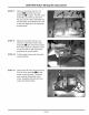
ERV/PRV Motor Wiring Kit Instructions STEP 4: Using a flat blade screwdriver, loosen the screw for the left “N1” (POWER INPUT) terminal inside the electrical access hole HY. It is the fourth one down from the top on the left side of the terminal block. STEP Remove the black and white wires from each other. 5: STEP 6: from the terminal block.
ERV/PRV Motor Wiring Kit Instructions STEP 8: Remove and retain the four (4) screws [MJ that hold the motor assembly IE in place. Pull the motor assembly out of the access hole. As you pull the motor assembly out, pull the black wire attached to it out of the hole leading to the electrical access panel. STEP 9: Remove and retain the four (4) screws on the back of the motor assembly i and remove the motor from the enclosure. Slide the wires out of the hole on the side of the enclosure as you remove it.
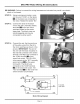
ERV/PRV Motor Wiring Kit Instructions WARNING: Failure to connect the wiring harnesses as instructed may result in an electric shock or fire hazard. STEP 12: Using a permanent marker, cross out the word “COM’, on the labels BRY on the black wire connected to the motor. Relabel the labels “NC”. STEP 13: Connect the ends of the black wire to the “NC” (normally closed) terminals on the two micro switches located on the motor base plate.
ERV/PRV Motor Wiring Kit Instructions STEP 15: Use the cable tie from the kit to bundle the wires on the end of the motor as shown. Trim the excess STEP 16: @ off the end. Re-insert the motor and base plate into the motor assembly enclosure, with the label R@ on the motor closest to the wire access hole B4. As you insert the motor, slip each of the wires into the hole on the side of the enclosure. STEP 17: Reattach the motor to the motor enclosure using the four (4) existing SCrews.
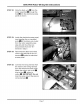
ERV/PRV Motor Wiring Kit Instructions STEP 18: Reinsert the motor assembly into the raised vent and reattach it using the existing screws. Insert the motor assembly so that the wires come out of the right side of the motor enclosure as you face the raised vent. Before tightening into place, make sure that the hole EE on the end of the lifting arm from the motor assembly is placed over the top of the pin on the bottom of the plenum &@.
ERV/PRV Motor Wiring Kit Instructions STEP 22: Slide the black wire Ing from the motor assembly Eis through the hole HEI into the electrical access panel as shown. STEP 23: Inside the electrical access panel, twist together the un-insulated ends EMM of the black wire routed from the motor assembly (see step 22) and the white wire disconnected from the “N1” terminal in step 5. STEP 24: Reconnect the black and white wires to the left side of the “N1” terminal EM inside the electrical access panel.
STEP 26: Use the remaining cable tie from the kit, bundle the wiring harnesses and stow them under the right edge of the access hole, away from the moving parts toward the center of the unit. STEP 27: Re-attach both access panels using the existing screws. STEP 28: Peel the backing off of the wiring diagram label included with the kit. Affix it to the front of unit, over the oN top of the existing label EN. STEP 29: STEP 30: Reconnect the unit to the electrical outlet.