
Installation guide


ERV/PRV
Motor
Wiring
Kit
Instructions
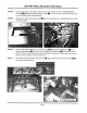
STEP
8:
Remove
and
retain
the
four
(4)
screws
[MJ
that
hold
the
motor
assembly
IE
in
place.
Pull
the
motor
assembly
out
of
the
access
hole.
As you
pull
the
motor
assembly
out,
pull
the
black
wire
attached
to
it
out
of
the
hole
leading
to
the
electrical
access
panel.
STEP
9:
Remove
and
retain
the
four
(4)
screws
on
the
back
of
the
motor
assembly
i
and
remove
the
motor
from
the
enclosure.
Slide
the
wires
out
of
the
hole
on
the
side
of
the
enclosure
as
you
remove
it.
STEP
10:
Cut
the
cable
tie
around
the
motor
wiring
harness.
STEP
11:
Disconnect
all
of
the
wires
from
the
two
(2)
micro
switches
ERM
on
the
motor
mounting
plate.
The
black
wire
remains
connected
to
the
motor.
Separate
the red
and
blue
wires
and
discard
them.
Page
3