
Installation guide


ERV/PRV
Motor
Wiring
Kit
Instructions
WARNING:
Failure
to
connect
the
wiring
harnesses
as
instructed
may
result
in
an
electric
shock
or
fire
hazard.
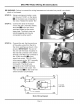
STEP
12:
Using
a
permanent
marker,
cross
out
the
word
“COM’,
on
the
labels
BRY
on
the
black
wire
connected
to
the
motor.
Relabel
the
labels
“NC”.
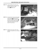
STEP
13:
Connect
the
ends
of
the
black
wire
to
the
“NC” (normally
closed)
terminals
on
the
two
micro
switches
located
on
the
motor
base
plate.
The
black
wires
are
interchangeable
and
may
be
connected
to
either
switch.
STEP
14:
Connect
the
red,
the
blue
and
one
of
the
yellow
wires
from
the
kit
to
the
micro
switches
as
shown
in
the
picture.
IMPORTANT:
The
end
of
the
wire
with
the
black
insulation
is
the
end
that
connects
to
the
switch
terminal.
The
RED
wire
connects
to
the
“COM”
terminal
MM
on
the
upper
limit
switch.
The
YELLOW
wire
connects
to
the
“NO”
(normally
open)
terminal
on
the
upper
limit
switch.
The
BLUE
wire
connects
to
the
“COM”
terminal
on
the
lower
limit
switch.
The
“NO”
terminal
on
the
lower
limit
switch
remains
unconnected.
RED
RED
UPPER
UMIT
SITCH
YEL
SS
To
electrical
ut
eer
L_BLK
access
panel
No
Connection
BLUE BLUE
Motor
Wiring
Diagram
Page
4