
Planning Guide

PLANNING
GUIDE
All specications subject to change without notice. www.dacor.com Ph. 800.793.0093
Heritage
®
30”, 36” Wide
Drop-In Gas Cooktop
Page 3 of 4
All tolerances: ±¹/₁₆” (±1.6 mm), unless otherwise stated.
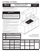
HCT305G, HCT365G
Configuration
A (Minimum/
Recommended)
B (Min. Interior Space
Betw. Combustible
Surfaces)
C (Min., Cutout
to Backsplash)
D (Cutout Depth) E (Cutout Width)
F (Min., Cutout
to Combustible
Side Wall)
HCT305G (no downdraft)
30” (76.2 cm)/
36” (91.4 cm)
29 ” (74.3 cm)
3 ” (8.3 cm) 19 ” (49.9 cm)
27 ”
(70.2 cm)
6 ” (17.5 cm)
HCT365G (no downdraft)
36” (91.4 cm)/
42” (106.7 cm)
35 ” (89.5 cm)
HCT305G (with MRV3015
downdraft)
30” (76.2 cm)/
36” (91.4 cm)
29 ” (74.3 cm)
” (1.0 cm) 22 ” (57.8 cm)
33 ”
(85.4 cm)
HCT365G (with MRV3615
downdraft)
36” (91.4 cm)/
42” (106.7 cm)
35 ” (89.5 cm)
Downdraft Compatibility
IMPORTANT: If installing cooktop with a
downdraft, install only the Dacor downdraft
models specified in the table below.
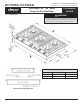
Cabinet and Countertop Layout
• Install the cooktop away from drafts caused by doors,
windows, and home ventilation outlets.
• The cooktop is to be used with a suitable vent hood or
approved Dacor downdraft-vent system.
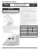
WARNING
• To reduce risk of burn injury from reaching over a hot cooktop,
avoid cabinet storage above the cooktop.
• Failure to comply with the max/min dimensions and clearances
in this guide may cause a fire hazard.
• Follow the countertop manufacturer’s instructions regarding
minimum corner radius, use of heat-reflective tape, corner
reinforcement, etc.
• Allow at least ” (6 mm) clearance between the bottom of
the cooktop chassis and all combustible surfaces, including
the upper edge of a drawer.
• The gas-supply piping, shut-off valve, and power outlet must not
interfere with the installed cooktop. If installing an appliance
below the cooktop, allow for routing of utilities behind it.
Installation must allow:
• access to the gas shut-off valve and regulator after installation.
• access to the electrical outlet when the cooktop is in place;
the 42” (106.7 cm) power cord must be able to reach the
electrical outlet
• access to the cooktop bottom for service/inspection
• clearance inside the cabinet for proper hold-down bracket
installation.
To allow access to the utilities and cooktop bottom, do not
install a fixed shelf below the cooktop. See the next page for
countertop cutout dimensions.
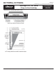
Callout Description
1 Measured from top of cooktop grate to combustible surface.
2
If installing an overhead vent hood, also check hood
specifications for minimum required clearances.
3
Not applicable for cabinets over 5 ” (14.0 cm) from either side
of cooktop edge; allow 6 ” (17.5 cm) from edge of cutout.