
Planning Guide


PLANNING
GUIDE
All specications subject to change without notice. www.dacor.com Ph. 800.793.0093
Heritage
®
30”, 36”, 48” Wide,
Dual-Fuel Ranges
Page 2 of 3
All tolerances: ±¹/₁₆” (±1.6 mm), unless otherwise stated.
HDPRS/HDERS
The wiring must be long enough that the range can be pulled out
for service, without being disconnected. Wiring to the range must:
• meet NEMA standards and the requirements in the above table
• include a strain relief
• be terminated by tinned leads, closed-loop terminals, or open-
ended spade lugs with upturned ends
• connect to a junction box or receptacle installed by a licensed
electrician.
The range may be connected via one of these two methods:
• 4-wire conduit connected to a 4-wire junction box
• 3-wire conduit (where local code permits, not for use with new
branch circuit installations) connected to a 3-wire junction box.
Using a power cord:
• A 4-wire power cord with a NEMA 14-50P plug connected to a
NEMA 14-50R receptacle:
• A 3-wire power cord (where permitted) with a NEMA 10-50P
plug connected to a NEMA 10-50R receptacle
• The power-cord plug must be UL listed type SRD or SRDT.
• Range models DYRP36D-C-S and DYRP48D-C-S come with a
factory installed 4-wire appliance cord with NEMA 14-50P plug.
For freestanding ranges installed in Canada, a factory installed
4-wire appliance cord with NEMA 14-50P plug is required,
without modification.
ELECTRICAL REQUIREMENTS
Model Required Circuit Total Connected Load
HDPR30S, HDER30S
240 Vac*, 60 Hz, 30 Amp. 5.75 kW (24.0 Amp.)
HDPR36S, HDER36S
HDPR48S, HDER48S 240 Vac*, 60 Hz, 50 Amp. 10.1 kW (41.9 Amp.)
*4-wire, two 120 Vac hot (L1 and L2), one neutral, one ground; these ratings are for
reference only; see the range's data label (back of range) for exact specications.
MINIMUM GAS-SUPPLY PRESSURE REQUIREMENTS*
Gas Type Min. Manifold Pressure Min. Gas-Supply Pressure**
Natural 5” water column 6” water column
LP (propane) 10” water column 11” water column
*Gas-supply pressure for testing the regulator setting shall be at least 1” water
column (249 Pa) above the specied manifold pressure; **Max gas-supply pres-
sure, all models: psi.
The above ratings are for reference only; see the rating label (upper-rear of
range) for exact specications.
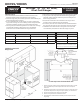
48” model shown
GAS-/ELECTRICAL-ACCESS DIMENSIONS
Model A B* C D* E**
HDPR30S/
HDER30S
3 ¼"
(8.3 cm)
27”
(68.6 cm)
6 "
(17.1 cm)
6
(17.1 cm)
”
(2.2 cm)
dia.
HDPR36S/
HDER36S
6 "
(17.1 cm)
27”
(68.6 cm)
12”
(30.5 cm)
HDPR48S/
HDER48S
4 ”
(10.8 cm)
27”
(68.6 cm)
9”
(22.9 cm)
*Measurement with range legs adjusted to their lowest height; **the hole
size for the electrical wiring may be increased to 1 ” (2.9 cm) by removing the
conduit bracket in the bottom of the electrical box.