Installation Instructions Renaissance ® Gas Range Models: RNRP30G THIS APPLIANCE HAS BEEN TESTED IN ACCORDANCE WITH THE LATEST EDITIONS OF ANSI Z21.1 STANDARDS FOR HOUSEHOLD APPLIANCES. Part No. 108801 Rev.
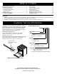
Table of Contents Important Safety Instructions...................................................... 1 Planning the Installation............................................................... 3 Electrical Requirements...............................................................3 Gas Supply Requirements........................................................... 3 Product Dimensions.....................................................................4 Cabinet Layout.........................................
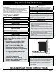
Important Safety Instructions Important Information About Safety Instructions The Important Safety Instructions and warnings in this manual are not meant to cover all possible problems and conditions that can occur. Use common sense and caution when installing, maintaining or operating this or any other appliance. Always contact the Dacor Customer Service Team about problems and conditions that you do not understand.
Important Safety Instructions WARNING • Read the accompanying use and care manual before operating this appliance. • Clean the cooktop thoroughly before operating it for the first time. • Keep packaging materials away from children. Plastic sheets and bags can cause suffocation. • • If you receive a damaged product, immediately contact your dealer or builder. Do not install or use a damaged appliance.
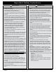
Planning the Installation WARNING • IMPORTANT: Observe all governing codes and ordinances during planning and installation. Contact your local building department for further information. • The installation of this appliance must conform with local codes or, in the absence of local codes, with the National Fuel Gas Code, ANSI Z223.1/NFPA 54. • To prevent an electric shock hazard, the power supply must meet the specifications stated below.
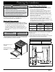
Planning the Installation Product Dimensions Product tolerances: ±1/16” (±1.6 mm) Front of open door Front of handle Front edge of bull nose Front panel Rear of front panel/oven door 48” (121.9 cm) 28 1/2” (72.4 cm) 26 7/8” (68.3 cm) 26” (66.0 cm) 24” (61.0 cm) 1 1/4” (3.2 cm) 1 1/16” (2.7 cm) to cooking surface (top of grates) 3” (7.62 cm) Standard backguard is 3” high. Optional 1.5” and 9” high backguards are available. Width: 29 7/8” (75.9 cm) 36 3/16” (91.9 cm) to 37 1/2” (95.
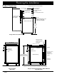
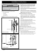
Planning the Installation Cabinet Layout • All maximum and minimum dimensions and clearances shown in the diagrams below must be maintained for safe operation. • Check the location where the range is to be installed. It should be placed away from drafts that may be caused by doors, windows and heating and air conditioning outlets. • To reduce accumulated smoke in the room, Dacor strongly recommends installation with a range hood or approved downdraft.
Planning the Installation Cutouts & Tolerances Cutout tolerances: +1/16” (+1.6 mm), -0 unless otherwise stated H J 27 1/2” (69.9 cm) 3 1/2” Backsplash non-combustible rear wall (recommended) 3/8" (1.0 cm) min. for downdraft cap clearance J H 10" (25.4 cm) min. to combustible side Note 2 walls above the range (on both sides) F G 13” (33.0 cm) max.5 Non-combustible surface along back wall recommended F G 36” (91.4 cm)* 30” (76.2 cm)** 30” (76.
Installation Instructions Preparing for Installation WARNING • If the gas or electric service provided does not meet the product specifications, do not proceed with the installation. Call the dealer, the gas supplier or a licensed electrician. • Before installing the range, you must locate and secure the anti-tip bracket to the floor. Installing Rear Trim If installing the range in the self-rimming configuration, or if the range will be used with a downdraft, install the rear trim piece first.
Installation Instructions Installing the Anti-Tip Bracket to the Floor WARNING To perform its intended function, the anti-tip bracket must be attached as instructed to the concrete slab or wood sub-floor that is below any floor coverings (including cement board). Do not attach the anti-tip bracket directly to floor coverings such as ceramic/asphalt tile or linoleum. Use the anchors and four (4) of the Phillips head screws when attaching the anti-tip bracket to a concrete sub-floor.
Installation Instructions Installing the Anti-Tip Bracket to the Wall 1. 2. Determine the suitability of wall mounting the anti-tip bracket. To use the wall mount option, the range front panel (excluding the bull nose) must not be more than 27 inches (68.6 cm) from the wall, and the bracket screws must be able to thread into the back wall’s interal base plate (see Inside the Back Wall).
Installation Instructions Removing the Oven Door Connecting the Gas WARNING WARNING • Do not attempt to disengage the hinge catches with the door(s) removed from the range. The hinge springs could release causing personal injury. • Make sure the gas supply valve is off and that the power cord to the range is disconnected prior to connecting the gas line. • Do not lift or carry the oven door(s) by the handle.
Installation Instructions Re-installing the Oven Door(s) Finalizing the Anti-Tip Installation WARNING To avoid personal injury or damage to the door from it falling off its hinges: Rear leg Back of range 1 1/4” * up * Distance to floor: 4 1/16” to 5 5/16” Anti-Tip Foot (location varies) down • Make sure that the notch on the bottom of each oven door hinge locks inside the receptacle before attempting to open the oven door.
Installation Instructions Installing the Burner Knobs WARNING Installing the range knobs in the wrong position may result in damage to the griddle included with the range. The knobs for the center burners are marked with the maximum griddle settings. NOTE: There is a “D”-shaped key on the back of the knobs that mate with a “D” on the valve stem. This key ensures that the knob controls, icons, and valve stem align and work together. There are three (3) different types of knobs supplied with the range.
Installation Instructions Assembling the Cooktop WARNING Never attempt to operate the range’s cooktop with any of the burner rings, burner caps or grates removed. Installing the Burners There are two types of burners: the Simmer-Sear burner (left) and the Standard burner (right). Refer to the illustrations and STEPS below when intalling the burners and grates. • Either type (color) of the burner caps may be used.
Installation Instructions Verifying the Correct Setup Before using the range, read the accompanying Use and Care Manual completely. It contains Important safety, service, and warranty information. 1. Before beginning this test procedure, ensure that all cooktop control valves are OFF, and all burner rings, burner caps, and grates are properly placed on the cooktop. 2. Turn the gas supply ON at the shut-off valve. 3. Plug the power cord into an electrical outlet.
Installation Instructions Installation Checklist WARNING • To ensure a safe and proper installation, the following checklist should be completed by the installer to ensure that no part of the installation has been overlooked. • Proper installation is the responsibility of the homeowner. The importance of proper installation of your Dacor range cannot be overemphasized.
Notes 16
Notes
Dacor ● 14425 Clark Avenue, City of Industry, CA 91745 ● Phone: (800) 793-0093 ● Fax: (626) 403-3130 ● www.dacor.