Installation Instructions Heritage Gas Range HGPR36S, HGPR48S Part No.
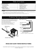
Table of Contents Important Safety Instructions...................................................... 1 Planning the Installation............................................................... 2 Electrical Requirements...............................................................2 Gas-Supply Requirements...........................................................2 Product Dimensions.....................................................................3 Cabinet Layout..........................................
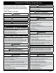
Important Safety Instructions Important Info About Safety Instructions The warnings throughout this manual cannot cover all possible issues. Use common sense and caution in installing and testing this range. Contact Dacor Customer Assurance about issues you cannot resolve. Safety Symbols and Labels DANGER Immediate hazards that WILL cause severe injury or death. WARNING Hazards/unsafe practices that COULD cause severe injury or death.
Planning the Installation Gas-Supply Requirements WARNING • IMPORTANT: Observe all governing codes and ordinances during planning and installation. Contact your local building department for further information. • To prevent an electric shock hazard, the power supply must meet the specifications stated below. It is the owner’s responsibility to make sure that the electrical service meets electrical requirements and that the electrical outlet has been properly installed by a licensed electrician.
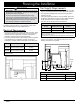
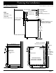
Planning the Installation Product Dimensions 48” (121.9 cm) 28 1/2” (72.4 cm) 26 7/8” (68.3 cm) 26” (66.0 cm) 24” (61.0 cm) Width HGPR36S: 35-7/8” (91.1 cm) HGPR48S: 47-7/8” (121.6 cm) Product tolerances: ±1/16” (±1.6 mm) Front of open door Front of handle Front edge of bull nose Front panel Rear of front panel/oven door 1 1/4” (3.2 cm) 1 1/16” (2.7 cm) to cooking surface (top of grates) 3” (7.62 cm) Standard backguard is 3” high. Optional 1.5” and 9” high backguards are available. 36 3/16” (91.
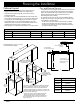
Planning the Installation Cabinet Layout Gas and Electrical Service • All maximum/minimum dimensions and clearances in the diagrams below must be maintained for safe operation. • Install the range away from drafts, and include a hood or approved downdraft. • For safety’s sake, do not install cabinets above the range; otherwise, install a hood that extends 5” or more past the cabinet face. • The range may be installed against the rear wall.
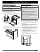
Installation Instructions Preparing for Installation WARNING • If the home gas/electric service does not meet product specifications, postpone installation until the gas supplier/ licensed electrician makes the appropriate modifications. • Before installing the range, install the anti-tip bracket. IMPORTANT: In the Commonwealth of Massachusetts, the range must be installed by a licensed plumber or gas fitter.
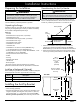
Installation Instructions 3. Determine the screw size required. The minimum full thread depth (portion of screw threaded into wood/slab) for wood is 3/8” (1 cm) and 5/8” (1.6 cm) for concrete. See SCREW SIZE TABLE to select the correct screw size. Anchoring the Bracket To Concrete 1. Drill four 3/8”-diameter countersink holes through any existing floor covering to (but not into) the concrete slab. 2. With a 3/16” masonry bit, drill four anchor holes 1-1/4” (3.2 cm) into the concrete slab.
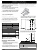
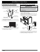
Installation Instructions Removing the Oven Door Connecting the Gas Make the range easier to move by detaching the door. WARNING • Do not try to disengage the hinge catches with the door removed. The springs could release causing personal injury. • Do not lift the door by its handle. NOTE: If installing the optional backguard, install it before sliding the range into place. (See page 5.) 1. 2. Open the door to its fully opened position.
Installation Instructions Finalizing Anti-Tip Installation 1. Peel the protective plastic from the range (including the door). 2. Measure from floor to countertop, and adjust the leveling legs as needed so the cooktop trim is even with or above the countertop. 3. Find the anti-tip foot on the back of the range, and turn it until it is 1/16” (2 mm) off the floor.
Installation Instructions Installing the Burner Knobs WARNING Incorrectly installing the burner-control knobs may lead to griddle damage from excessive heat. Knobs for the center burners have the MAX GRIDDLE setting.
Installation Instructions Assembling the Cooktop WARNING Do not use the cooktop unless all burner components and grates are properly in place. • The range uses standard and SimmerSear burners. • Use porcelain or brass burner caps as you prefer. • When assembling the burners, rotate/adjust each part until it seats securely in place for proper function. • Gently set the grates in the spill tray so the feet of each grate rest in their corresponding dimples formed into the spill tray.
Installation Instructions Verifying Proper Function Moving the Range for Service Before using the range, read the User Manual completely. It contains important safety, service, and warranty information. Before starting, turn off all range controls, and verify that all cooktop components are properly in place.. 1. 2. 3. 4. 1. 2. 5. Open the gas-supply valve. Plug in the range. The oven indicator light blinks for 10 seconds. (When the blinking stops, go to Step 3. 3.
Notes
Notes
Dacor ● 14425 Clark Avenue, City of Industry, CA 91745 ● Phone: (800) 793-0093 ● Fax: (626) 403-3130 ● www.dacor.