Installation Instructions Heritage Induction Pro Range HIPR30S, HIPR36S Part No.
Table of Contents Before You Begin 3 Important Notes Customer-Assurance Information 3 3 Important Safety Instructions 4 Safety Symbols and Cautionary Information Installation-Related Safety Instructions 4 5 Consignes de sécurité importante 7 Symboles de sécurité et informations de mise en garde Instructions de sécurité relatives à l'installation 7 8 Product Specifications 9 HIPR30S, HIPR36S Ranges Included Accessories Needed Tools 9 10 10 Installation Requirements 11 Pre-installation Check
Before You Begin Important Notes Installer • Read this manual thoroughly before installing the range. • Remove all packaging before connecting the electric and gas supplies. • Observe all governing codes and ordinances. • Leave this manual with the owner; write the unit’s model/serial numbers inside for reference. • Installation of the range requires basic mechanical skills. Owner • As with any heat-generating appliance, certain precautions must be followed.
Important Safety Instructions Safety Symbols and Cautionary Information Electrical equipment can be dangerous if handled improperly. The Important Safety Instructions in this manual are intended to minimize the risk of property damage, personal injury, and death. Carefully follow the instructions in this manual. SAFETY SYMBOLS/ALERTS Hazards/unsafe practices that may result in severe personal injury or death. Hazards/unsafe practices that may result in personal injury or property damage.
Important Safety Instructions Installation-Related Safety Instructions • Read these instructions thoroughly to reduce the risk of property damage, fire, personal injury, and death, and to ensure proper installation. • These safety instructions cover installation-related safety issues. For use-and-care-related safety instructions, including general use, electrical, cooktop, and oven safety, see the User Manual. Installation-Specific Safety • Remove all tape and packing material.
Important Safety Instructions Installation-Related Safety Instructions, cont. Read these instructions thoroughly to reduce the risk of property damage, fire, personal injury, and death, and to ensure proper installation. Fire Safety • Do not store/place/use combustible items (e.g., paper, plastic, fabrics, gasoline) near the range. • Do not wear loose-fitting or hanging garments or accessories while using the range. • Regularly clean the oven vents. • Do not use a towel or other bulky cloth as a pot holder.
Consignes de sécurité importantes Symboles de sécurité et informations de mise en garde L'équipement électrique peut être dangereux s'il n'est pas manipulé correctement. Les consignes de sécurité importantes (pages 7 à 9) ont pour but de minimiser le risque de dommages matériels, de blessures corporelles et de mort. Suivez attentivement ces instructions. SYMBOLES DE SÉCURITÉ / ALERTES Dangers/pratiques dangereuses pouvant entraîner des blessures graves ou la mort.
Consignes de sécurité importantes Instructions de sécurité relatives à l'installation • Lisez attentivement ces instructions pour réduire les risques de dommages matériels, d'incendie, de blessures corporelles et de mort, et pour assurer une installation correcte. • Ces consignes de sécurité couvrent les problèmes de sécurité liés à l'installation.
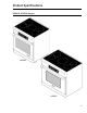
Product Specifications HIPR30S, HIPR36S Ranges HIPR30S HIPR36S 9
Product Specifications Included Accessories GlideRackTM Oven Rack (2) Standard Oven Rack (1) Anti-Tip Bracket w/Screws and Anchors Temperature Probe (1) Griddle (1) Broiler Pan and Grill Stainless-Steel Cleaner Literature Kit Slotted Screwdriver Phillips Screwdriver Nutdriver Needle-Nose Pliers Open-End or Adjustable Wrench Pencil, Ruler Level Utility Knife Needed Tools 10
Installation Requirements Pre-Installation Checklist FF FF FF FF Before installing the range, read this manual thoroughly. Plan for a location where the range will not be subject to strong drafts. Remove packaging from the range. Verify that all items are present before beginning the installation. General Requirements Clearances and Dimensions • For safe operation, provide adequate space between the range and combustible surfaces.
Installation Requirements General Requirements, cont. Product Dimensions (tolerances: ±¹/₁₆” or ±1.6 mm) HIPR30: 29 7/8” (75.9 cm); HIPR36: 35 7/8” (91.
Installation Requirements General Requirements, cont. Cabinet Dimensions Maintain all max/min dimensions and clearances in the diagrams below. CUTOUT DIMENSIONS Model F—recommended/min G—min/max H—downdraft cutout width HIPR30 36” (91.4 cm)/30” (76.2 cm) 30” (76.2 cm)/30 1/8” (76.5 cm) 27 3/8" (69.5 cm) HIPR36 42” (106.7 cm)/36” (91.4 cm) 36” (91.4 cm)/36 1/8” (91.8 cm) 33 1/2” (84.8 cm) Standard Cutout for Range Hood Cutout tolerances: ±1/16” (±1.
Installation Requirements Location Requirements Electrical Hookups (HIPR 30”, 36”) ELECTRICAL-ACCESS DIMENSIONS Model A HIPR30 6 3/4" (17.1 cm) HIPR36 12” (30.5 cm) B* C** 6 3/4 (17.1 cm) 7/8” (2.2 cm) dia. *Range legs adjusted to lowest height; **hole size may be increased to 1 1/8” (2.9 cm) by removing conduit bracket in bottom of electrical box. Electrical Service Inlets • Existing utilities may be used if they meet the spec's in this manual.
Installation Instructions Preparing for Installation • If the gas or electric service provided does not meet the product specifications, discontinue installation, and call the dealer, gas supplier, or a licensed electrician. • Before moving the range into place, install the anti-tip bracket (see below for instructions). Unpacking the Range Unpack the parts box, and verify that all specified components are present (see Pg. 9 or 10). If any item is missing or damaged, contact your dealer immediately.
Installation Instructions Preparing for Installation, cont. Installing the Anti-tip Bracket and Foot, cont. Floor-Mounting the Anti-tip Bracket, cont. • Determine the anti-tip bracket location (see the diagram below). Mark the 4 hole locations on the floor. • Determine screw size. Minimum full thread depth (portion of screw threaded into the sub-floor) is 3/8” (1 cm) for wood and 5/8” (1.6 cm) for concrete. (See the SCREW SIZE table, below, for correct screw sizes.
Installation Instructions Preparing for Installation, cont. Installing the Anti-tip Bracket and Foot, cont. Wall-Mounting the Anti-tip Bracket For this option to be suitable, the forward edge of the range's front panel must be 26 1/2” (67.3 cm) or less from the wall, and the bracket screws must be able to engage the base plate inside the wall. Notches on the sides of the bracket indicate the minimum height of the base plate to ensure secure threading. Using product dimensions on Pg.
Installation Instructions Preparing for Installation, cont. Removing the Oven Door So the range is easier to move, remove the door(s) to reduce the weight. • Do not try to disengage the hinge catches with the door(s) removed. The hinge springs could release, causing personal injury. • Do not lift or carry the oven door(s) by the handle. If using a backguard, install it (Pg. 17) before sliding the range into place. 1.
Installation Instructions Making the Electrical Connection • Wire the range according to local ordinances. • Improperly connected electrical wiring can lead to electric shock and appliance damage. Dacor is not responsible for damage due to improper electrical connection. • Connect the ground terminal (or lead) on the range to a grounded, metallic, permanent wiring system or grounding conductor. • Do not use an extension cord, which may result in fire and personal injury.
Installation Instructions Making the Electrical Connection, cont. Connecting the Conduit to the Range For instructions on how to connect the power cord, see Pg. 24. 1. Remove the range's electrical-access cover (see left). 2. (4-wire only) Loosen the grounding screw (E), and remove the neutral-to-ground jumper link (D). 3. Remove the conduit’s strain-relief nut (J). 4. Slide the wires and the end of the strain relief into the hole on the bottom of the range’s electrical box. 5.
Installation Instructions Making the Electrical Connection, cont. Connecting the Conduit to the Home Junction Box Do not connect the range’s green wire to the neutral (white) supply wire unless local code allows. • The power supply must be properly polarized so the burner igniters do not keep sparking after ignition. • If you are unsure the power supply is properly polarized/grounded, have it checked by a licensed electrician. 1.
Installation Instructions Final Installation Installing the Anti-tip Foot 1. Peel the protective coating from all range surfaces. 2. Measure from floor to countertop. Adjust the leveling legs so the cooktop trim is flush with or above the countertop. 3. At the bottom-left rear of the range, lower (rotate) the anti-tip foot until it is ¹/₁₆” (2 mm) off the floor. 4. Carefully slide the range into place in the cutout. 5. With a flashlight, verify that the the anti-tip foot engages the anti-tip bracket. 6.
Installation Instructions Verifying Proper Operation • Before operating the range, read the User Manual completely to familiarize yourself with important safety, service, and warranty information. • This procedure instructs you how to verify the function of the oven and each cook zone on the cooktop. See the User Manual for verification of other features. • Use a ferrous (magnetic) pot/pan partially filled with water when verifying cook zones.
Dacor – 14425 Clark Avenue, City of Industry, CA 91745 – Phone (800) 793-0093 – Fax (626) 403-3130 – www.dacor.