Installation Instructions Discovery ® Touch-Control Induction Cooktop Models DYTT305N and DYTT365N Part No. 109374 Rev.
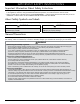
TABLE OF CONTENTS Important Safety Instructions........................................... 1 Important Information About Safety Instructions............... 1 About Safety Symbols and Labels.................................... 1 General Precautions......................................................... 1 Installation Specifications................................................. 3 Electrical Specifications.................................................... 3 Location Requirements.........................
IMPORTANT SAFETY INSTRUCTIONS Important Information About Safety Instructions • The Important Safety Instructions and warnings in this manual do not cover all possible issues and conditions relative to the appliance; therefore, during installation/maintenance/operation, be cautious and use common sense. • Always contact Dacor Customer Service (see If You Need Help…, previous page) when issues arise that you do not understand or cannot resolve via the Installation Manual and Use and Care Manual.
IMPORTANT SAFETY INSTRUCTIONS General Precautions, cont. WARNING • Concerning cooktop service/maintenance: -- Before installing/servicing the unit, switch power off at the service panel, then lock the panel to prevent power from being switched on. If the panel cannot be locked, securely/prominently fasten a warning device (e.g., tag) to the service panel. -- Clean/maintain the cooktop regularly as instructed in the Use and Care manual; a dirty cooktop is a possible fire hazard.
INSTALLATION SPECIFICATIONS Electrical Specifications IMPORTANT The cooktop’s electrical-connection lead wires may be a smaller gauge than is installed in your home; however, the National Electric Code and local inspection authority specify that smallergauge wire is compatible with the larger-gauge wire. • The owner shall ensure that a licensed electrician installs the electrical supply for the cooktop. • The electrical installation (incl.
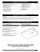
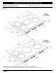
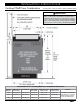
INSTALLATION SPECIFICATIONS Appliance Dimensions All tolerances: ±1/16 (±1.6 mm), unless otherwise stated This section contains pertinent appliance dimensions that will help you plan for the countertop cutout and under-counter clearances. • Chassis depth is 1/2” wider and deeper at the base of the glass cooking surface. • The cooking surface overhangs the top of the chassis by 3/4” (1.9 cm) in front, back, all around.
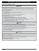
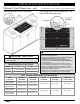
INSTALLATION SPECIFICATIONS Cabinet Cutout Dimensions All tolerances: ±1/16 (±1.6 mm), unless otherwise stated See the next page for flush- and downdraft-installation cutouts. Cabinet Clearances Callout Model A B DYTT305 30” (76.2 cm) 28 3/4” (73.0 cm) DYTT365 36” (91.4 cm) 34 3/4” (88.3 cm) Description 1 30” min. clearance from cooktop surface and bottom of unprotected wood or metal cabinet 2 Distance to combustible side wall (either side): 2 1/4” (5.7 cm) min.
INSTALLATION SPECIFICATIONS Cabinet Cutout Dimensions, cont. Countertop Inset-Cutout Dimensions All tolerances: ±1/16 (±1.6 mm), unless otherwise stated Countertop Flush-Cutout Dimensions—for Down-Draft Vent (top view) IMPORTANT (Flush Cutout for Down-Draft Vent) IMPORTANT (Inset Cutout) See the previous page for minimum clearances to combustibles and overhead cabinets. Width Dimensions (Inset Cutout) Model A B DYTT305 30 1/8” (76.5 cm) 28 3/4” (73.0 cm) DYTT365 36 1/8” (91.8 cm) 34 3/4” (88.
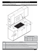
INSTALLATION INSTRUCTIONS Cooktop/Wall-Oven Combination All tolerances: ±1/16 (±1.6 mm), unless otherwise stated IMPORTANT When installing a DTO, DYO, or RNO wall oven with a DYTT cooktop, you cannot use a downdraft vent system. Because standard floor-cabinet depth is 24”, and the wall oven depths are all 24”, there is no space for the downdraft vent behind the cooktop. A hood venting system must be used when installing a wall oven under a DYTT cooktop in standard-depth cabinets.
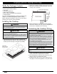
INSTALLATION INSTRUCTIONS Verify the Package Contents Verify that all these items have been included: • DYTT Induction Glass Cooktop • Foam tape • Hold-down brackets (2) • Glass scraper (PN 82499) • Dacor Cooktop Cleaning Creme (PN A300) • Product literature If any item is damaged/missing, contact your dealer immediately. Do not install a damaged/incomplete cooktop. Before starting the installation, make sure you have all the equipment you need for proper installation. 2.
INSTALLATION INSTRUCTIONS Connecting the Cooktop Wiring, cont. Three-Wire Electrical Connection IMPORTANT No white-wire connection is needed for this 3-wire appliance. If the junction box has a neutral (white) wire, you must shield it to comply with the National Electrical Code. 1. Separate the wires coming out of the appliance conduit. 2. Connect the black wire from the appliance conduit to the black (L1) supply wire in the junction box. 3.
INSTALLATION INSTRUCTIONS Verifying Proper Operation Troubleshooting This procedure instructs you how to verify the basic operation of each cook zone. See the Use and Care Manual to verify operation of other features. Use a ferrous (magnetic) pot/pan, and perform this procedure for all cook zones. If the cooktop does not operate properly: • verify that power is supplied to the cooktop and that all electrical connections proper and secure. • repeat the Verifying Proper Operation procedure.
WIRING DIAGRAM 11
WIRING DIAGRAM 12
NOTES 13
NOTES 14
NOTES 15
Dacor ● 14425 Clark Avenue, City of Industry, CA 91745 ● Phone: (800) 793-0093 ● Fax: (626) 403-3130 ● www.dacor.