Installation Instructions Heritage Wall-Mount Range Hoods HWHE30/36/48; HWHP30/36/48 ® APPROVED FOR USE WITH ALL DACOR RANGES AND COOKTOPS. TESTED IN ACCORDANCE WITH THE LATEST EDITION OF ANSI/UL 507 STANDARD FOR ELECTRIC FANS AND CAN/CSA-C22.2 NO. 115 STANDARD FOR FANS AND VENTILATORS. Part No. 113917 Rev.
Table of Contents Important Safety Instructions........................................... 1 Important Information About Safety Instructions............... 1 General Safety Precautions.............................................. 2 Product Specifications ..................................................... 3 General Specifications...................................................... 3 Weight Specifications........................................................ 3 Dimensions...............................
Important Safety Instructions Important Information About Safety Instructions Safety Symbols and Labels DANGER • The Important Safety Instructions and warnings in this manual cannot cover all possible issues. Use common sense and caution when installing the hood. Immediate hazards that WILL result in severe personal injury or death. WARNING • Contact Dacor Customer Assurance about issues you cannot resolve (contact information on previous page).
Important Safety Instructions General Safety Precautions To reduce the risk of fire, electric shock, serious injury, or death when using your range hood, follow basic safety precautions, including these: WARNING • Use the hood only as outlined in this manual. Do NOT use the hood to vent hazardous/explosive materials or vapors. If you have questions, contact Dacor (contact info on Pg. 1). • If you receive a damaged product, immediately contact your dealer/builder. Do not install/use a damaged hood.
Product Specifications General Specifications Weight Specifications All Models: HWHP, HWHE Individual Models: HWHP, HWHE Features Blower Speeds Filters Exhaust(s) Total Connect Load Lights Description Model Weight 3012 51 lbs. (23 kg) 3018, -3612 53 lbs. (24 kg) 8-in. duct diameter 3618 57 lbs. (26 kg) 120V, 60 Hz, 9 Amp. Max. (10.0 Amp Max. surge) Dimmable LED: PAR16 E26/27; 120V, 7.5W (75W Max. other bulbs) 4812 70 lbs. (32 kg) 4818 77 lbs.
Product Specifications Dimensions (Electrical/Ductwork Connections) Connect electrical wires and ductwork through the top or rear of the hood. Before installing the hood, mark the access holes according to the diagrams below. (Tolerances: ±1/16” unless otherwise stated.) Dimensions: Top Electrical Access Holes (HWHP, HWHE) Model A B C 48 1 1/2 in. (3.81 cm) 5 in. (12.7 cm) 3 in. (7.62 cm) 36 1 1/2 in. (3.81 cm) 4 1/2 in. (11.43 cm) 3 in. (7.62 cm) 30 1 1/2 in. (3.81 cm) 5 1/2 in. (13.
Product Specifications Dimensions Tolerances: ±1/16” unless otherwise stated. Single Blower: HWHP 30, 36 Series Single Blower: HWHE 30, 36 Series Dual Blower: HWHP 48 Series Dual Blower: HWHE 48 Series HWHE Hood Dimensions HWHP Hood Dimensions Model A 3012 29 7/8” (75.9 cm) 3612 35 7/8” (91.1 cm) 4812 47 7/8” (121.6 cm) 3018 29 7/8” (75.9 cm) 3618 35 7/8” (91.1 cm) 4818 47 7/8” (121.6 cm) B C D Model A B C D 24” (61 cm) 12” (30.48 cm) 11 7/8” (30.2 cm) 3012 29 7/8” (75.
Preparation and Setup Parts List Part Hood (models vary in size/ appearance) Grease channel Needed Tools/Hardware Qty Example 1 Have these items available before starting the installation.
Preparation and Setup • See the diagram below: Top/Rear Electrical Access Holes for wire hole locations inside the hood. • See Wiring Diagrams at the end of this document. Meeting Installation Requirements WARNING Observe local ordinances regarding all facets of the project during planning and installation. Contact the local building department for details. IMPORTANT See the diagram for minimum installed distance from hood bottom to cooking surface.
Preparation and Setup Planning the Ductwork WARNING • To keep combustion byproducts, smoke, or odors out of the home, and to improve efficiency, tape all duct joints securely. • Range hoods may impede flow of smoke and combustion gases from furnaces, gas waterheaters, and fireplaces. To avoid drawing lethal gases into the home, follow manufacturer directions for these devices and NFPA/ASHRAE recommendations.
Preparation and Setup • Support the weight of the ducting with sheet-metal screws as needed. • To prevent backdraft, a damper at the duct outlet may be required. WARNING • Electricity to the range hood should be installed only by a licensed electrician. • Observe all governing codes and ordinances during site preparation and installation. Contact your local building department for details. • Improperly anchoring the hood to the wall may cause personal injury if unit falls.
Installation Instructions Marking the Centerlines These measurements and marks are for centering and leveling the hood, marking the duct cutouts, and installing the holding brackets (which brackets temporarily support the hood as you mount it permanently). IMPORTANT Users of the dual-exhaust format will need to install the AHT10 Dual-to-Single Transition Kit. (See the section Using the Dual-to-Single Transition Kit #AHT10 on Page 12 for installation instructions.
Installation Instructions Installing the Holding Brackets, cont. Holding-Bracket Centerline Distance HWHP, HWHE A 3012, 3018 12 1/2 in (31.8 cm) 3612, 3618 7 1/8 in (18.1 cm) 4812, 4818 17 in (43.2 cm) Rotating the Blower(s) for Rear Exhaust Perform this procedure before you hang the hood. WARNING • Only install the hood if the electrical service provided meets the hood’s specifications. • Observe all governing codes and ordinances during installation.
Installation Instructions Rotating the Blower(s) for Rear Exhaust, cont. 3. Unscrew the cable clamp(s), and remove the hardware that holds the blower and L-bracket (previous graphic). 4. Detach the blower and plate, and place them nearby. The images in this section were chosen to illustrate the intended information and may not exactly represent the hood being installed. Orientating the Blower/Vent L-Brackets 1. Unscrew, and remove the L-bracket that is in the default top-venting orientation.
Installation Instructions Rotating the Blower(s) for Rear Exhaust, cont. Orientating the Blower(s) The blower(s) must be correctly positioned. Ensure the blower I/O port is against the back of the hood. Compare it with this graphic: Blower tip extends here Assembling the Filters Filters are boxed separately and must be assembled during installation. All needed knobs and hardware are included with the filters. For correct orientation, ensure the top of the filter faces up.
Installation Instructions Using the Dual-to-Single Transition Kit #AHT10 Bending the Flange (18”-Tall Hoods) • Top vent: Models 3018, 3618, 4818 • Rear vent: Models: 3018, 3618, 4818 On dual-exhaust models, the two 8” duct exhausts can be transitioned into one 10” duct. Assemble the Dacor transition kit #AHT10 (sold separately) before you hang the hood. This transition kit fits over the top/rear ventilation exits.
Installation Instructions Hanging the Hood WARNING Hanging the range hood requires two people. Do not lift the hood unassisted. IMPORTANT Take care not to scratch/damage the hood. 1. Remove the plastic film from the hood. Rear-Vent Configuration 2. Drill screwholes in the flanges, being sure to pierce the hood top. 3. With sheet-metal screws, fasten the AHT10 unit to the hood. 4. With foil tape/duct tape, seal the AHT10 unit’s base.
Installation Instructions 5. (If needed) Mark the top of the hood if the configuration calls for the hood to be secured at the top. 6. Remove the hood from the wall. 7. Drill the pilot or anchor holes. (If using anchors, insert them into the anchor holes.) 8. Re-engage the hood to the holding brackets. 9. Adjust the hood into its final position, and fasten it in place: Hardwiring the Hood WARNING Hardwiring the Hood, cont.
Installation Instructions WARNING • • • Do not ground the circuit to a gas line. Do not ground the circuit to a hot water pipe. Insulated water lines must be jumped to assure continuity to the ground. (See below.) Separate No. 10 (minimum) copper ground wire To house circuit breaker panel or fuse box Meter Wire nut, 3 places WHITE WHITE GREEN GREEN Fasten clamp tightly on metal pipe No.
Installation Instructions Verifying the Setup c. 1. Turn OFF the main power switch. ON OFF 2. Turn power ON at the circuit panel or fusebox. 3. Turn ON the main power switch. The button panel flashes several times during startup. 4. Insert the filters gently: a. Do not scratch the back of the grease channel! b. Set the front edge into the clip, and press forward. Main Power Switch Detail/ Hood Bottom 5. 6. 7. 8. 9.
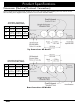
Wiring Diagrams HWHP3012, -3018; HWHE3012, -3018 WIRING DIAGRAM: HWHP/HWHE Wiring Diagram: 1-Blower, 2-Light Models 19
Wiring Diagrams HWHP3612, -3618; HWHE3612, -3618 WIRING DIAGRAM: HWHP/HWHE Wiring Diagram: 1-Blower, 3-Light Models 20
Wiring Diagrams HWHP4812, -4818; HWHE4812, -4818 WIRING DIAGRAM: HWHP/HWHE, RNHP/RNHE Wiring Diagram: 2-Blower, 4-Light Models 21
Dacor ● 14425 Clark Avenue, City of Industry, CA 91745 ● Phone: (800) 793-0093 ● Fax: (626) 403-3130 ● www.dacor.