36” R e f r i g e r ato rs For Use With: EF36 version P-A IF36 version P-A Part No. 100502/13036903 Rev.
Table of Appliance Safety...........................................................................1 Installation Recommendations....................................................1 Design Specifications...................................................................2 Product Dimensions.....................................................................2 Door Swing Dimensions..............................................................2 Installation Specifications...................................
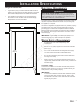
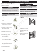
Design Specifications Product Dimensions ◊ The depth from the front of the door (w/o door handles) to the back of the refrigerator chassis is 27 1/8” (689mm). ◊ The depth of the cabinet less door is 24” (610mm). ◊ The power cord is 40” (1016mm) long.
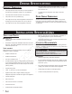
Installation Specifications Electrical Requirements Rough-In Dimensions ◊ ◊ A grounded 3 prong non-GFCI electrical outlet should be placed 2” (51mm) from the right side cabinets or end panel. See “Electrical Requirements” for additional information. The plumbing for the water line can come through the floor flush to or from the back wall. See “Water Supply Requirements” for more information. WARNING Electrical shock Hazard – Plug into a grounded 3prong non-GFCI outlet. Do not remove ground prong.
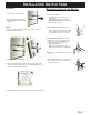
Door Installation Instructions and Drawer Removal Pullout Freezer Drawer Some installations require door/drawer removal to transport the refridgerator to it’s final location. warning Danger To prevent accidental child entrapment or suffocation risk, do not remove the divider in the top freezer basket. To avoid electrical shock which can cause severe personal injury or death, observe the following: • Disconnect power to refrigerator before removing doors or drawer.
Installation Instructions To Install: Reinstallation of the Doors 1. Pull both rails out to full extension. 2. While supporting door front, hook supports into slots located on inside of each slide. Note • All four drawer bracket supports must be in the proper slots for the drawer to function properly. 1. Install hinge assemblies: • Install top hinge loosely with 5/16” hex headscrews. • Install center hinge with Phillips screws. • Freezer door models: Install bottom hinge with 3/8” hex head screws.
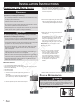
Connecting Installation Instructions the Water Supply warning 3. Place brass nut (A) and sleeve (B) on copper tube end as illustrated. Reminder: Do not use an old sleeve. The nut and sleeve are provided in the use and care packet. To reduce the risk of injury or death, follow basic precautions, including the following: • Do not attempt installation if instructions are not understood or if they are beyond personal skill level. • Observe all local codes and ordinances. 4.
Move Unit Installation Instructions to Final Position IMPORTANT: To prevent floor damage, make sure levelers are raised (not touching the floor) and the unit is on rollers before moving. ◊ Place top of cardboard carton or plywood under refrigerator. Remove unit from dolly. ◊ Move the refrigerator straight back and evenly into the rough opening. Verify that the water tubing is not kinked and the power cord is not kinked.
Service Information If you need service, be sure to have the model and serial numbers when you call. You’ll find these numbers on the serial number plate located above the light shield in the fresh food compartment. Contact a Dacor® authorized Servicer, a Dacor® dealer, or the Dacor® Customer Service Department at 800.793.0093 or email customerservice@dacorworld.
Web Site: Phone: www.dacor.com (800) 793-0093 The information and images in this book are the copyright property of Distinctive Appliances, Inc. Neither this book nor any information or images contained herein may be copied or used in whole or in part without the express written permission of Distinctive Appliances, Inc. ©Distinctive Appliances, Inc. all rights reserved.