
Installation guide

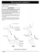

Planning
the
Installation
1%"
(45
mm)
Min.
e e
clear
to
top
of
door
for
heat
1%"
(45
mm)
Min.
clear
to
top
of
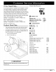
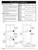
Selecting
the
Location
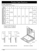
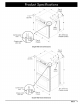
Model
A
3 C D
=
Number
*
Carefully
check
the
location
where
the
oven
is
tobe
[9497
installed.
The
oven
should
be
placed
for
convenient
PO127
, , ,
access,
but
away
from
drafts
that
may
be
caused
25
1/2
27
96
1/2
by
doors,
windows,
and
heating,
ventilation
and
air
=[MOV127
(648
mm)
|
(686
mm)
|
(1435
mm)
conditioning
outlets.
MOH127
27
7/16"
+
Make
certain
that
electrical
power
can
be
provided
EO130
(697
mm)
Setanat
erent
ore
oven
doormen
tisin
=
zee!
|
sor
|
62
2
the
open
position,
MOV130
(724
mm)
|
(762
mm) |
(1588
mm)
.
MOV130
+
Plan
the
installation
so
that
all
minimum
clearances
[.PO227
25
1/2”
27”
are
met
or
exceeded.
Cutout
dimensions
shown
MOV227
(648
mm)
|
(686
mm)
proviee
minimum
clearances,
unless
otherwise
MOH227
50
9/16”
NA
.
E0230
(1284
mm)
*«
The
specified
minimum
cabinet depth
and
width
PO230
, ,
must
be
provided.
The
cabinet
depth
and
width
28
1/2
30
must
completely
enclose
the
recessed
portion
of
MOV230
(724
mm)
|
(762
mm)
the
oven.
MOH230
*
Cabinet
cutout
dimensions
must
be
used
as
indi-
cated.
€£$
C¢
——________»
$$
©
—_________»
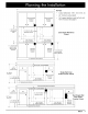
Recommended
Recommended
electrical electrical
location location
|
‘uC
‘oy
t
t
i
“
|
1°
(25
Min.
|
Mince
|!
Single
Wall
Seat
|
Double
Wall
bottom
Oven
Cutout
bottom
of
Oven
Cutout
of
door
1
OA
door
~«—t
B-———+]
|
Alternate
|
an
electrical
/
3/4”
(19
mm)
location
1
A
\
/
Support
platform
;
‘
Y
<1
_
oe
I
I
I
I
I
31
1/4”
(794mm)
door
for
heat
A
exhaust
oor
for
hea
,
recommended
exhaust
/
3/4”
(19
mm)
(may
be
altered)
Support
platform
'
9
5/8”
(244
mm)
recommended
(may
be
altered)
f
r
|
ky
t
e
4"
Typical
toe kick
(shown)
4"
Typical
toe kick
(shown)
6
dacor