
Installation guide
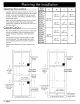

Planning
the
Installation
~<
D
>|
|
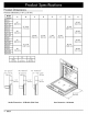
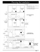
NOTES:
*
Cutout
tolerances:
1/16”,
-O
(1.6
mm,
-0)
24”
minimum
cutout
depth
Recommended
Recommended
.
3/4”
support
platform
must
be
flush
with
electrical
electrical
front
of
cutout.
See
page
8.
location
location
‘Ne
‘
|
el|e el\e
a
>
1°
(25
mm)
Mi
to
bottom
of
4"
(102
mm)
Min.
+>
I
I
I
I
door
|__|
Between
cutouts
Duel
Single
Wall
Oven
I
I
I
I
Y
1
A
1A
Cutout
~t
B
+]
et
B
+»
\
-
=—|_—_
eee
ee
ee
=
CF
-
—|—_
ee
ee ee
Se
=
/
3/4”
(19
mm)
/
3/4”
(19
mm)
|
LO
y
support
platform
.
¥
support
platform
1%"
(45
mm)
Min.
/ /
clear
to
top
of
door
for
heat
Alternate
Alternate
exhaust
electrical
electrical
|
31
1/4”
(794
mm)
location location
recommended
os
may
be
altered)
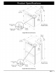
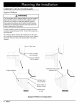
4°
Typical
toe kick
(shown)
{
|
y
t
1"
(25
mm)
Min.
to
combustibles
)
41/2”
(38
mm
Typical
counter
Single
Wall
Oven
36”
Typical
A
'
(914
mm)
.
B
Under-Counter
Cutout
~
Recommended
1
%*
(45
mm)
Min.
WL
electrical
to
combustible
floor
y
,
3/4”
(19
mm)
location
Y
|
ay
y
support
platform
A
.
Y
4"
Typical
toe
kick
(shown)
|
Recommended
electrical
location
+f
1*
(25
mm)
Min.
to
combustibles
T T
41/2"
I I
(38
mm)
e
|
;
e
Typical
counter
I
4°
(102
mm)
Min.»
|
|
between
cutout
|
.
e
‘
Duel
Single
Wall
36”
Typical
1A
tA
Oven
Under
(914
mm)
~_!
B——_»|
|«—!
3B»
\
—
—_J
NY
Counter
Cutout
1%*
(45
mm)
Min.
Pio]
Pio
Alternate
to
combustible
floor
y
.
3/4”
(19
mm)
y .
3/4”
(19
mm)
electrical
y
|
”
y
support
platform
7
y
support
platform
locations
A
.
y
4"
Typical
toe kick
(shown)
dacor
7