I n sta l l ati o n I n stru c ti o n s Wa r m i n g O v en For use with models: EW, EWO MW, MWO PW, PWO IWO, IOWO Part No. 65034 Rev.
Table of Important Safety Instructions...................................................... 1 Design Specifications................................................................2-3 Product Dimensions..................................................................2-3 Installation Specifications.........................................................4-6 Installation Planning..................................................................4-5 Power Supply Requirements..................................
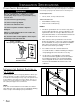
Important Safety Instructions Important Information About Safety Instructions Safety Symbols and Labels DANGER Important Safety Instructions and warnings appearing in these instructions are not meant to cover all possible conditions and situations that can occur. Common sense, caution and care must be exercised when installing, maintaining or operating an appliance. Immediate hazards that WILL result in severe personal injury or death.
Design Specifications Product Dimensions NOTE: All tolerances are + 1/16,” - 0” unless otherwise stated.
Design Specifications Overall Dimensions (IWO, IOWO) 40" (1016mm) 3 prong 120 Vac power cord Mounting holes (rear holes IOWO model only) F C Chassis view without drawer Drawer Face Dimensions (IWO Shown) Chassis Dimensions (IOWO Shown) E Chassis K G NOTE: Only model IOWO24 warming ovens are approved for outdoor use. They are designed for installation of a custom designed drawer front or for the Dacor Epicure® drawer front and handle. Order accessory model number AEWP24 through your Dacor dealer.
Installation Specifications Installation Planning ◊ A qualified technician must complete the installation of this built-in appliance. Proper installation is the responsibility of the customer. ◊ Carefully check the installation location. The oven should be placed for convenient access. Make certain that electrical power can be provided in the selected location. ◊ Plan the installation so that all minimum clearances are met or exceeded.
Installation Specifications Typical countertop Cooktop 1 1/2" (38mm) Warming Oven C 3/4" Min. (19mm) 5/8" Min. (16mm) 36" Typ. (914mm) A B 120 Vac electrical outlet Single Installation to Side of Cooktop OB Outdoor Grill EG Epicure Gas Cooktop Warming Oven 36" typ. (914mm) Warming Oven C 120 Vac electrical outlet 3/4" Min. (19mm) D C 5/8" Min.
Installation Specifications Power Supply Requirements The correct voltage, frequency and amperage must be supplied to the electrical outlet from a grounded, single phase circuit that is protected by a properly sized circuit breaker or time-delay fuse. WARNING Electric shock Hazard – This appliance is equipped Circuit Requirements: with a 40” (1016mm) power cord with a three prong grounded plug. Plug it only into a grounded three prong electrical outlet. ◊ 120 Vac, 60 Hz, 15 Amp. dedicated circuit.
Installation Instructions Verifying the Package Contents • Use and care manual • Mounting screws • Wire rack with mounting hardware (IOWO model only) Removing the Drawer Installing the Chassis WARNING To avoid personal injury caused by the appliance falling forward when the drawer is opened, secure the chassis to the cabinet and support platform as instructed. WARNING 1.
Installation Instructions Re-installing the Drawer 1. Pull the drawer slides all the way out of the drawer opening. 2. Gently lower the drawer between the extended slides until the drawer is suspended by the slide rails. 3. Slide the back of the drawer mounting brackets under the drawer mounting clips on the slides. 4. Push the side of the drawer down onto its locking tab, until the tab locks into place. 5. Repeat the same process on the opposite side. 6.
Dacor ● 1440 Bridge Gate Drive, Diamond Bar, CA 91765 ● Tel: (800) 793-0093 ● FAX: (626) 403-3130 ● www.Dacor.