Installation Instructions Renaissance Wall Mount Range Hoods ® Models RNHP30, RNHP36, and RNHP48 ® APPROVED FOR USE WITH ALL DACOR RANGES AND COOKTOPS. TESTED IN ACCORDANCE WITH THE LATEST EDITION OF ANSI/UL 507 STANDARD FOR ELECTRIC FANS AND CAN/CSA-C22.2 NO. 115 STANDARD FOR FANS AND VENTILATORS. Part No. 109172 Rev.
Table of Contents Important Safety Instructions........................................... 1 Important Information About Safety Instructions............... 1 General Safety Precautions.............................................. 2 Product Specifications ..................................................... 3 General Specifications...................................................... 3 Weight Specifications........................................................ 3 Dimensions...............................
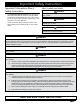
Important Safety Instructions Important Information About Safety Instructions • • Safety Symbols and Labels DANGER The Important Safety Instructions and warnings in these instructions are not meant to cover all possible problems and conditions that can occur. Use common sense and caution when installing, maintaining or operating this or any other appliance. Always contact the Dacor Customer Service Team about problems and conditions that you don’t understand.
Important Safety Instructions CAUTION For general ventilating use only. Do not use to exhaust hazardous or explosive materials and vapors. General Safety Precautions To reduce the risk of fire, electric shock, serious injury or death when using your appliance, follow basic safety precautions, including the following: WARNING • Do not install or operate this hood if it has been damaged, dropped, has damaged electrical wires or is not working properly.
Product Specifications General Specifications Weight Specifications All Models Individual Models Features Blower Speeds Filters Exhaust(s) Total Connect Load Lights Description Model Weight Four (4) RNHP3012 51 lbs. (23 kg) Baffle style, dishwasher safe 8-inch duct diameter 120V, 60 Hz, 9 Amp. Max. (10.0 Amp Max. surge) Dimmable LED: PAR16 E26/27 120V, 7.5W (75W Max. other bulbs) RNHP3018 RNHP3612 53 lbs. (24 kg) RNHP3618 57 lbs. (26 kg) RNHP4812 70 lbs. (32 kg) RNHP4818 77 lbs.
Product Specifications Dimensions Electrical and Ductwork Connections Connect electrical wires and ductwork through the top or rear of the hood. Before installing the hood, mark the access holes according to the diagrams below. Top Connections: Electrical and Duct Dimensions Single Exhaust Models** Standard 8-inch duct Dual Exhaust Models* Standard 8-inch duct Back of hood Electrical access holes 7/8 in dia. (5.1 cm) 5 3/4 in (14.61 cm) CL A B C See Top Access Holes table on right page.
Product Specifications Dimensions Tolerances: +1/16” -0” unless otherwise stated. Single Blower: RNHP30 & RNHP36 Series Dual Blower: Model RNHP48 Series D D A A C C B B Hood Dimensions Model A RNHP3012 29 7/8” (75.9 cm) RNHP3612 35 7/8” (91.1 cm) RNHP4812 47 7/8” (121.6 cm) RNHP3018 29 7/8” (75.9 cm) RNHP3618 35 7/8” (91.1 cm) RNHP4818 47 7/8” (121.6 cm) B C D 24” (61 cm) 12” (30.48 cm) 11 7/8” (30.2 cm) 24” (61 cm) 18” (45.7 cm) 11 7/8” (30.
Preparation and Setup Parts List A Hood (1) B Grease channel (1) C Baffle-style filter with knobs (ready-to-assemble kit) (2-4) D Hood Model LED Lights Bafle-Style Filters RNHP48 RNHP36 RNHP30 4 3 2 4 3 2 pictures vary by model A Holding brackets and hardware (2) E Dimmable LED light bulbs (2-4) F Light replacement tool (1) G Literature (2) I Dacor Cleaning Creme (1) B C D E G F I STAINLESS STEEL CLEANER Necessary Tools and Hardware Please make sure these tools and hardware
Preparation and Setup Installing the Electrical Source Meeting Electrical Codes WARNING Make sure electrical service to the range hood is installed by a licensed electrician. It is the owner’s responsibility to confirm that all electrical requirements are met by a qualified electrician who is is servicing this appliance.
Preparation and Setup Meeting Installation Requirements WARNING Observe all governing codes and ordinances during planning and installation. Contact your local building department for further information. Use only ductwork deemed acceptable by state, municipal and local codes. E Electrical access top rear WARNING To reduce the risk of personal injury caused by reaching over a hot appliance, cabinet storage space located directly above the range should be avoided. 30” min.* (76.
Preparation and Setup Planning the Ductwork A WARNING • To prevent combustion by-products, smoke or odors from entering the home and to improve efficiency, tape all duct joints securely. • Range hoods may interrupt the proper flow of smoke and combustion gases from furnaces, gas water heaters, and fireplaces. To avoid drawing lethal gases into the home, follow the manufacturer’s recommendation for these devices and consult NFPA and ASHRAE recommendations.
Preparation and Setup Ductwork Tips Wherever possible, reduce the number of transitions, turns, and sharp angles. Two staggered 45° angles are better than one sharp 90° angle. • The hood exhaust connects to an 8-inch round duct. You can increase the duct size over the duct run if desired. Keep turns as far away from the hood exhaust as possible, and keep as much space between any bends as possible. • To prevent a backdraft, never decrease the duct size over the run.
Preparation and Setup Preparing the Mounting Location WARNING • The electricity to the range hood should be installed only by a licensed electrician. • Observe all governing codes and ordinances during site preparation and installation. Contact your local building department for further information. • Failure to properly anchor the hood to the wall may result in personal injury due to the unit falling off the wall.
Installation Instructions Marking the Centerlines Top Exhaust These measurements and marks are for centering and leveling the hood, marking the duct cutouts, and installing the holding brackets. The holding brackets temporarily hold the hood while you mount it permanently into place. Have a marking tool, tape measure, and level ready. 1. Position the hood in the same orientation as it will be when installed. (For example, if it is a top vent installation, set the hood with the vents on top.) CL 2.
Installation Instructions Installing the Holding Brackets Holding Bracket Cenerline Distance IMPORTANT: Placing the holding brackets above, below, or off the centerline will cause alignment problems during final installation. Models 1. Mark the holding bracket’s horizontal centerline 2 1/8 inches (54 cm) below the top of the hood. 2. Next, mark the holding bracket’s two vertical centerlines. Refer to the table and image on right. F RNHP3012, RNHP3018 12 1/2 in (31.
Installation Instructions Rotating the Blower(s) for Rear Exhaust WARNING • Do not install the range hood unless the electrical service provided meets the range hood specifications. • Observe all governing codes and ordinances during installation. Contact your local building department for further information. • A qualified technician must complete the installation of this built-in appliance. More than one person is required to raise the hood into place.
Installation Instructions Rotating the Blower(s) for Rear Exhaust Various models illustrate these instructions, so the images presented might not be an exact replication of the hood being installed. Step 1 However, the best illustrations were chosen to help communicate the intended information. Instructions: Back of Hood Disassembling Parts 1. Unhook and remove the grease channel. 2. Place the hood assembly on a large, flat surface. Take special care not to scratch the hood. 3.
Installation Instructions Rotating the Blower(s) for Rear Exhaust Orientating the Blower/Vent L-Brackets 9. Unscrew and remove the L-bracket that is in the default top-venting orientation. Step 9 10. Turn and align the L-bracket so the hole is in back of the hood, allowing a rear-venting configuration. Top of Hood continued...
Installation Instructions Rotating the Blower(s) for Rear Exhaust Orientating the Blower(s) Steps 11-12 It is imperative that the blower(s) are installed in the correct orientation. To do this, make sure the bower I/O port is against the back of the hood. Confirm the placemet is correct by comparing it with the figures on the right. Blower tip extends here 11. Roll the hood on its top so the tip of the blower can extend beyond the exit vent. Back of Hood 12.
Installation Instructions Assembling the Filters Filters are boxed separately and must be assembled during installation. All knobs and hardware that is needed is included with the filters. To ensure the correct orientation, make sure the top of the filter lays face-up. The face of the filter has: • plastic peel-away coating • beveled lip on the inside frame • screw holes up on the ridge (not down in the trough) Instructions 1. Remove the plastic coating and confirm that the inside lip is beveled.
Installation Instructions Using the Dual to Single Transition Kit# AHT10 Bending the Flange for: • Top Vent Configuration: None. Rear Only On dual exhaust models, the two 8-inch duct exhausts can be transitioned into one 10-inch duct. Assemble the Dacor transition kit # AHT10 before hanging the hood. This transition kit fits over the top or rear ventilation exits. • Rear Vent Configuration On models 3012, 3612, 4812 • Notes: 12” hood height requirement Keep one of the long edges straight! 2” (5.
Installation Instructions Installing the AHT10 Top Vent: 3012, 3612, 4812 3018, 3618, 4818 Top Vent: 3012, 3612, 4812 3018, 3618, 4818 1. Drill holes on the flanges for metal screws. Make sure the holes pierce the top of the hood (see right). 2. Center the transition kit over the duct collars. 3. Fasten the kit into place using sheet metal screws (not included). 4. Seal the base of the transition kit with foil tape or duct tape.
Installation Instructions Hanging the Range Hood WARNING Hanging the range hood requires two people. Do not attempt to lift the hood without assistance. When hanging the hood, be careful not to scratch or damage the hood. 1. Remove the plastic film from the hood. There are hanging slots in the back of the hood a few inches from the top. The holding brackets on the wall engage here and temporarily hold the hood in place. Holding brackets 2.
Installation Instructions Hardwiring the Hood WARNING • To avoid electric shock or fire hazard, prior to connecting the electrical wiring to the hood, make sure that power to the hood power supply line is turned off at the fuse box or circuit breaker panel. • Improper connection of the hood electrical wiring may create an electric shock or fire hazard and may result in damage to the hood’s electrical system. See page 7 for specifications.
Installation Instructions WARNING • Do not ground the circuit to a gas line. • Do not ground the circuit to a hot water pipe. • Water lines that are insulated must be jumped to assure continuity to ground. See below. To house circuit breaker panel or fuse box Wire nut, 3 places Separate No. 10 (minimum) copper ground wire WHITE WHITE GREEN GREEN Fasten clamp tightly on metal pipe BLACK BLACK Meter No.
Installation Instructions Verifying the Setup FAN button LIGHTS button TIMER button OFF ON Main Power Switch Feature Button Panel 1. Make sure the main power switch is OFF. (Refer to the figures at right.) FRONT 2. Turn power ON at the circuit panel or fuse box. 3. Then turn the main power switch ON. The control panel will flash several times during startup. Feature button pamel 4.
Installation Instructions The Installation Checklist WARNING • To ensure a safe and correct installation, the following checklist should be completed by the installer to ensure that no part of the installation has been overlooked. • Proper installation is the responsibility of the homeowner. The importance of proper installation of your Dacor range hood cannot be overemphasized.
Wiring Diagrams RNHP3012, RNHP3018 WIRING DIAGRAM: RNHP 3012, 3018 HOOD LIGHT 75W HOOD LIGHT 75W Y W Y W WIRE COLOR CODE W -WHITE B -BLACK Y -YELLOW O -ORANGE R -RED BL -BLUE BR -BROWN G -GREEN V -VIOLET B BL Y B WR O B R W BL W W 10 9 8 7 6 5 4 3 2 1 P2 K3 K2 K1 K4 POWER SWITCH B B MICROPROCESSOR PROGRAMMING HEADER 2 4 6 8 10 P3 BLOWER 455W, 115V COIL COM 13579 NO RESISTOR 6 2 0 Ω, 1/4W 4 RELAY HOOD POWER and CONTROL BOARD 11 10 9 8 7 6 5 4 3 2 1 BR W W W W W W W W W R RESISTOR 3.
Wiring Diagrams RNHP3612, RNHP3618 WIRING DIAGRAM: RNHP 3612, 3618 HOOD LIGHT 75W HOOD HOOD LIGHT 75W LIGHT 75W Y W Y W Y W WI RE CO LOR CODE W -WH I TE B -BLA CK Y -YE LLO W O -ORA N GE R -RE D B L -BLU E B R -BRO WN G -GRE E N V -VI O LE T B Y B WR O B R W BL W W 10 9 8 7 6 5 4 3 2 1 P2 K3 K2 K1 K4 POWER SWITCH B B BLOWER 455W, 115V MICROPROCESSOR PROGRAMMING HEADER 2 4 6 8 10 P3 COIL COM 13579 NO RESI STOR 6 2 0 Ω, 1 /4 W 4 RELAY HOOD POWER and CONTROL BOARD 11 10 9 8 7 6 5 4 3 2 1
Wiring Diagrams RNHP4812, RNHP4818 WIRING DIAGRAM: RNHP 4812 & 4818 HOOD LIGHT 75W HOOD HOOD LIGHT 75W LIGHT 75W Y W BL B O R B W Y W Y W HOOD LIGHT 75W Y W W I R E C OL OR C O DE W -WHI TE B -B L A CK Y -YE L L OW O -OR A N G E R -R E D B L -B L U E B R -B R OWN G -GR E E N V -V I OL E T BL O R O Y B WR O B W R W BL W W 10 9 8 7 6 5 4 3 2 1 P2 K3 K2 K1 K4 POWER SWITCH B B BLOWER 455W, 115V BLOWE R 455W, 115 V MICROPROCESSOR PROGRAMMING HEADER 2 4 6 8 10 P3 COIL COM 13579 NO R
Notes 29
Dacor ● 14425 Clark Avenue, City of Industry, CA 91745 ● Phone: (800) 793-0093 ● Fax: (626) 403-3130 ● www.dacor.