Installation Instructions Renaissance ® Gas Range Models RNRP36G, RNRP48G THIS APPLIANCE HAS BEEN TESTED IN ACCORDANCE WITH THE LATEST EDITIONS OF ANSI Z21.1, UL858 AND UL60730-1, STANDARDS FOR HOUSEHOLD APPLIANCES. Part No. 108531 Rev.
Table of Contents Important Safety Instructions...................................................... 1 Planning the Installation............................................................... 3 Electrical Requirements...............................................................3 Gas Supply Requirements........................................................... 3 Product Dimensions.....................................................................4 Cabinet Layout.........................................
Important Safety Instructions Important Information About Safety Instructions The Important Safety Instructions and warnings in this manual are not meant to cover every possible problem and situation that can occur. Use common sense and caution when installing, maintaining, or operating this or any other appliance. Always contact the Dacor Customer Service Team about problems and conditions that you do not understand.
Important Safety Instructions WARNING • Read the accompanying use and care manual before operating this appliance. • Clean the cooktop thoroughly before operating it for the first time. • Keep packaging materials away from children. Plastic sheets and bags can cause suffocation. • • If you receive a damaged product, immediately contact your dealer or builder. Do not install or use a damaged appliance.
Planning the Installation Gas Supply Requirements WARNING • IMPORTANT: Observe all governing codes and ordinances during planning and installation. Contact your local building department for further information. • The installation of this appliance must conform with local codes or, in the absence of local codes, with the National Fuel Gas Code, ANSI Z223.1/NFPA 54. • To prevent an electric shock hazard, the power supply must meet the specifications stated below.
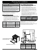
Planning the Installation Product Dimensions Various Dimensions of Range (Side View) Width RNRP36G: 35 7/8” (91.1 cm) RNRP48G: 47 7/8” (121.6 cm) Product tolerances: ±1/16” (±1.6 mm) Front of open door Front of handle Front edge of bull nose Front panel Rear of front panel/oven door 48” (121.9 cm) 28 1/2” (72.4 cm) 26 7/8” (68.3 cm) 26” (66.0 cm) 24” (61.0 cm) 1 1/4” (3.2 cm) 1 1/16” (2.7 cm) to cooking surface (top of grates) 3” (7.62 cm) Standard backguard is 3” high. Optional 1.
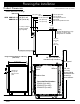
Planning the Installation Cabinet Layout • All maximum and minimum dimensions and clearances shown in the diagrams below must be maintained for safe operation. • Check the location where the range is to be installed. It should be placed away from drafts that may be caused by doors, windows and heating and air conditioning outlets. • To reduce the risk of fire or personal injury from reaching over a hot appliance, avoid cabinet installations directly above the range.
Planning the Installation Gas and Electrical Service Range Model Downdraft Vent Model RNRP36G ERV36-ER RNRP48G ERV48-ER Range Model 1.5” Low-Profile Backguard Model RNRP36G APB36GLP RNRP48G APB48GLP • The shaded area shown below denotes the location of the gas inlet and the electrical outlet. This is the recommended location. For replacement purposes, the location of the existing utilities may be utilized provided they do not interfere with the sides or rear of the range.
Installation Instructions Preparing for Installation WARNING • • If the gas or electric service provided does not meet the product specifications, do not proceed with the installation. Call the dealer, the gas supplier or a licensed electrician. Before installing the range, you must locate and secure the anti-tip bracket to the floor. IMPORTANT: Within the Commonwealth of Massachusetts, this appliance must be installed by a licensed plumber or gas fitter.
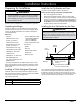
Installation Instructions Installing the Anti-Tip Bracket on the Floor (cont.) 1. Determine the location of the range center line and front panel for the range’s final position based on the Product Dimensions on page 5 and the actual cabinet/cutout dimensions used for the installation. 2. Determine the required position of the anti-tip bracket, based on the diagram below. Mark the four (4) mounting hole locations on the floor with a pencil. 3. Determine the screw size required.
Installation Instructions Installing the Anti-Tip Bracket on the Wall 1. Determine the suitability of wall mounting the anti-tip bracket. To use the wall mount option, the range front panel (excluding the bull nose) must not be more than 27” (68.6 cm) from the wall and the bracket screws must be able to thread into the base plate inside the wall behind.
Installation Instructions Removing the Oven Door Gas Connection WARNING WARNING • Do not attempt to disengage the hinge catches with the door(s) removed from the range. The hinge springs could release causing personal injury. • • Do not lift or carry the oven door(s) by the handle. Make sure the gas supply valve is off and that the power cord to the range is disconnected prior to connecting the gas line. • NOTE: When installing a backguard, always install it before sliding the range into place.
Installation Instructions Final Installation Re-installing the Oven Door(s) 1. Peel the protective plastic coating off of the range, including the door. 2. Measure from the floor to the countertop. Adjust the leveling legs as required to position the trim around the cooktop even with or above the countertop. 3. Locate the anti-tip foot on the back of the range and lower (turn) it until it is 1/16” (2 mm) off the floor.
Installation Instructions Installing the Burner Knobs WARNING Installing the range knobs in the wrong position may result in damage to the griddle included with the range. The knobs for the center burners are marked with the maximum griddle settings. NOTE: When installing the knobs, align the “D” shaped opening on the back of the knob with the end of the valve shaft. Carefully push the knob on until it stops. There are three (3) different types of knobs supplied with the range.
Installation Instructions Cooktop Assembly WARNING Never attempt to operate the range’s cooktop with any of the burner rings, burner caps or grates removed. • Remove the burner rings, burner caps and grates from their shipping packages. • Install the burners as shown. Either type (color) of the supplied burner caps may be used. When installing the burner components, twist each piece back and forth slightly until it drops completely into place.
Installation Instructions Verifying Proper Operation Before operating the range, read the accompanying use and care manual completely. It contains Important safety, service and warranty information. 1. Before beginning the test procedure, ensure that all cooktop control valves are in the OFF position, and all burner rings, burner caps, and grates are properly positioned on the cooktop frame. 2. Turn on the gas supply at the shut-off valve. 3. Connect the power cord to the electrical outlet.
Dacor ● 14425 Clark Avenue, City of Industry, CA 91745 ● Phone: (800) 793-0093 ● Fax: (626) 403-3130 ● www.dacor.