Service Manual XGA COLOR MONITOR Model : 710B DAEWOO ELECTRONICS CO., LTD OVERSEAS SERVICE DEPT.
CONTENTS SAFETY PRECAUTIONS 1 GENERAL SAFETY INFORMATION 2 SERVICING PRECAUTIONS 3 TECHNICAL INFORMATION 6 GENERAL INFORMATION 7 PIN CONNECTOR 8 CAUTIONS FOR ADJUSTMENT AND REPAIR 8 OPERATION & ADJUSTMENT 9 TROUBLESHOOTING HINTS 15 ALIGNMENT PROCEDURE 31 BLOCK DIAGRAM 33 PCB LAYOUT 34 SCHEMATIC DIAGRAM 37 EXPLODED VIEW DIAGRAM 38 REPLACEMENT PARTS LIST 39 CIRCUIT BOARD ELECTRICAL PARTS LIST 40
SAFETY PRECAUTIONS CAUTION: No modifications of any circuit should be attempted. Service work should only be performed after you are thoroughly familiar with all of the following safety check and servicing guidelines. Safety Check Care should be taken while servicing this analog color display because of the high voltages used in the deflection circuits. These voltages are exposed in such areas as the associated flyback and yoke circuits.
GENERAL SAFETY INFORMATION Terms in the manual CAUTION Statements identify conditions or practices that could result in damage to the equipment or other property. WARNING Statements identify conditions or practices that could result in personal injury or loss of life. Terms as marked on equipment CAUTION Statements indicate a personal injury hazard not immediately accessible as one reads the marking, or a hazard to properly including the equipment itself.
SERVICING PRECAUTIONS CAUTION: Before servicing instruments covered by this service manual, its supplements and addendum, read and follow the SAFETY PRECAUTIONS of this manual. NOTE: If unforeseen circumstances create conflict between the following servicing precautions and any of the safety precautions on page 1 of this manual, always follow the safety precautions. Remember: Safety First. General Servicing Precautions 1. Always unplug the AC power cord from the AC power source before: a.
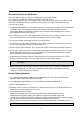
Electrostatically Sensitive (ES) Devices Some semiconductor (solid state) devices can be damaged easily by static electricity. Such components commonly are called Electrostatically Sensitive (ES) Devices. The examples of typical ES devices are integrated circuits, some field-effect transistors and semiconductor “chip” components. The following techniques should be used to help reduce the incidence of component damage caused by static electricity. 1.
FIGURE 1. USE SOLDERING IRON TO PRY LEADS IC Removal/Replacement Some utilized chassis circuit boards have slotted (oblong) holes through which the IC leads are inserted and then bent flat against the circuit foil. When holes are slotted, the following technique should be used to remove and replace the IC. When working with boards using the familiar round hole, use the standard technique as outlined in paragraphs 5 on the page under the title of general soldering guidelines. Removal 1.
Power IC, Transistor or Devices Removal/Replacement 1. Heat and remove all solders from the device leads. 2. Remove the heatsink mounting screw (if applicable). 3. Carefully remove the device from the circuit board. 4. Insert new device in circuit board. 5. Solder each device lead, and clip off excess lead. 6. Replace heatsink. Diode Removal/Replacement 1. Remove defective diode by clipping its leads as close as possible to diode body. 2. Bend the two remaining leads perpendicularly to the circuit board.
GENERAL INFORMATION This color monitor automatically scans all horizontal frequencies from 30KHz to 69KHz, and all vertical frequencies from 50Hz to 160Hz. This color monitor adopted the OSD (On Screen Display), it shows the sync polarity and frequency and it provides that easily adjust control.
PIN CONNECTOR Pin Signal 1 2 3 4 5 6 7 8 9 10 11 12 13 14 15 Red Green Blue GND GND GND - Red GND - Green GND - Blue Reserved GND - H.Sync GND Bi-directional Data (SDA) Horizontal Sync Vertical Sync (VCLK) Data Clock (SCL) 1 6 10 15 Arrangement of 15-pin D-sub connector CAUTIONS FOR ADJUSTMENT AND REPAIR • Degaussing is always required when adjusting purity or convergence. • The white balance adjustment has been done by a color analyzer in factory.
OPERATION & ADJUSTMENT ADJUSTMENT KEY Launch OSD(On-Screen Display) menus Select the next function Increase the value of any selected function Decrease the value of any selected function 9
ADJUSTMENT PROCESS R G B R G B BRIGHTNESS 50% CONTRAST 50% R G B R G B PINCUSHION 50% TRAPEZOID 50% R G B R G B K K COLOR TEMP. 9300 RED GAIN 6550 50% R G B R G B ZZ Z ZZ RECALL NO YES STATUS H : +31.5KHZ V : +70.5 HZ When you choose the icon Z on the OSD window, you can exit the OSD screen.
OSD(On-Screen Display) Menu 1 CONTRAST 50% Adjust the contrast of image, the difference between light and dark areas on the screen. Range : 0-100% Adjust the brightness of the entire display. BRIGHTNESS 50% H.POSITION 50% Adjust the position of the display horizontally (left or right). Adjust the display width (horizontal size). H.SIZE 50% V.POSITION 50% Adjust the position of the display vertically (up or down). Adjust the display height (vertical size). V.
OSD(On-Screen Display) Menu 2 Adjust the left and right margins for more convex or more concave margins. • Image turns to by . • Image turns to by - . TRAPEZOID 50% PARALLELOGRAM 50% PIN BALANCE 50% V. MOIRE 50% ROTATION 50% Adjust the trapezoid of the screen by moving the lines inward or outward. • Image turns to by . • Image turns to by - . Adjust parallelogram when the screen is leaning left or right. • Image turns to by . • Image turns to by - .
OSD(On-Screen Display) Menu 3 Choose different preset color temperatures or set your own customized color parameters. Adjust the red gain. RED GAIN 50% Adjust the green gain. GREEN GAIN 50% Adjust the blue gain. BLUE GAIN 50% Adjust the red bias. RED BIAS 50% Adjust the green bias. GREEN BIAS 50% Adjust the blue bias. BLUE BIAS 50% OSD(On-Screen Display) Menu 4 STATUS H : +31.5KHZ V : +70.5 HZ Display horizontal & vertical frequency and polarity.
Self Diagnosis When the monitor doesn’t display, if you press any key, Self Diagnosis screen is displayed. Self Diagnosis function checks if the status of the monitor is No Signal or Out of range. No Signal screen is displayed when the D-Sub signal connector is not connected or the status of the monitor is on DPMS mode. Out of Range screen is displayed when the applied frequency is under or over normal range.
TROUBLESHOOTING HINTS 1.
2. No Raster No Raster Is CRT heater red-hot? Is Heater Voltage (CRT PWB) about 6V? No Yes No Trouble in CRT Yes Trouble in power supply circuit Turn the Brightness & Contrast control to set Maximum Refer to trouble in power supply unit.
3. A missing Color One color is missing Is input signal normal? No Check video signal cable or video card. No Trouble in IC801 or its ambient circuit No Is video output IC803 waveform normal? 0.
4. Abnormal OSD Font Abnormal OSD Font Is menu key selected? Is OSD Font exist? * If menu key selected. Is Heater Voltage (CRT PWB) about 6V? No Yes Yes One color is missing Troubie in IC802 or its ambient circuit Yes Is the output of IC802 (pin 13, 14, 15) normal? No Trouble in IC802 and its ambient circuit Yes Refer to Missing Color 18 No Trouble in Heater voltage line. Refer to trouble in P.S.
5. Horizontal Output Circuit Trouble in Horizontal output circuit (No Raster Is the B+line voltage over 45V? No Trouble in B+ Booster Circuit (Check the B+section of IC501, Check Q603 and its ambient circuit). Yes Is the H-out waveform of IC501 normal? 11V 0V No Trouble in IC501 Yes Is the Collector wave form of Q501 or Q502 normal? 10V 0V No Trouble in Q501, Q502 Yes Is the Collector waveform of Q503 normal? 66V Yes Trouble in Q504 and its ambient circuit.
6. Unstable Picture 6-1. Horizontal Unstable picture Is H.Sync input pin of IC501 correct? No Check H.Sync Out of Micom or its ambient circuits.
6-2. V.OSC/Deflection Circuit Unstable or Abnormal picture Is ± 13V DC line correct? No Trouble in power supply unit Yes 45Vp-p Is the output waveform of IC401 (pin 6) normal? Yes V.DY failure Yes Trouble in IC401 or its ambient circuit No Is the output pulse of IC501 (pin 23) normal? No Trouble in V.Sync line or IC501 failure.
7.
7-1. Dynamic Focus FVH FVV * Check after adjusting the static focus finely by VR in FBT Focus is poor PHILIPS : 440V 180V NEC : 300V 120V SAMSUNG : 300V 120V DF waveform FVH FVV Is the waveform of the DF pin in FBT correct? Yes 1. Check the CRT socket or connector wire 2. Trouble in FBT or CRT No 1. Check the waveform of the pin 3 of FBT. 2. Check D575 No 1. Check the 12V DC line. 2. Check Q751,D755 No Is the cathode voltage of the D575 about 600V? Yes Is the base voltage of the Q751 about 2.
8. Convergence Poor convergence Is convergence on the center area bad? Yes Adjust static convergence Refer to Adjustment procedure of convergence No Is convergence on the fringe area bad? Yes Adjust D.
9. Abnormal Picture 9-1. Horizontal Size Abnormal H.Size When the VR601 is changed, is the H.size changed? No Check pin 15 of IC501 and its ambient circuit (D604, R605, R606, R607) Yes Is the H.Size about 295mm at VGAmode and Min. H.Size in OSD Menu? No Yes It isn't out of order. 25 1.Check B+ section of TDA9109 and its ambient circuit. 2.Check Q601 and its ambient circuit.
9-2. Vertical Size Abnormal V.Size Is changeable the DC voltage of IC401 pin 1? No Is the 3.5Vdc of pin 23 of the IC501? Yes Trouble V.OSC/ Deflection Circuit No Check the IC501 and its ambient circuit Refer to V.
10. High Voltage Circuit Trouble in H.V circuit (No Raster) Is B+(45V) line voltage normal? No Trouble in power supply circuit Yes Trouble in Q574 or FBT Yes Trouble in Q572, Q573 12V Line Yes Is Q574 base waveform normal? No Is Q571 collector waveform normal? No Is Q501 emitter waveform normal? Yes Trouble in Q571 No Is IC501 pin 26 waveform normal? Yes Trouble in Q501, Q502 No Is IC501 pin 29 voltage about 12V? No Trouble in power supply Yes Is the input H.
11. Side-Pincushion Circuit Side-Pincusion distortion is excessive or barrel Select the side-pincushion icon on OSD menu, and adjust acceptable position. Yes O.K No Is the pin 24 waveform of IC501 correct Yes Check IC501 or their ambient circuit (pin 14, 15, 16) Yes Check IC501 or it's ambient circuit. No Is the waveform of IC501 pin 1, 2 No Trouble in H.
12. Power Supply Unit (P.S.U) Trouble in P.S.U Is power switch on? No Switch on Yes Is fuse F001 O.K? No Check the power cord outlet and diode D001, D002, D003, D004 No Replace R004 Replace C005 No Trouble in D001, D002, D003, D004, C004 and TH001. No Trouble in T001, IC001, IC101, PH001 and D005 etc.
A Is voltage of C104 13V DC? No Trouble in D104, IC102 or horizontal Part. No Trouble in D105 or vertical Part. Yes Is voltage of C105 -13V DC? Yes Is voltage of C106 8.7V DC? No Trouble in D106 or Q103 Yes P.S.U O.
ALIGNMENT PROCEDURE Standard Adjustment Conditions 1. Power source voltage : AC 120V, 60Hz./AC 220V, 50Hz 2. Aging : Take at least 20 minutes warm-up time. 3. Signals. Video : Analog 0.7Vpp 75 terminal positive polarity Synchronizing : TTL level Negative/Positive Separate/Composite Deflection frequency Horizontal Frequency : 30KHz - 69KHz Vertical Frequency : 50Hz - 160Hz Pre-Adjustment 1. High voltage Adjustment Adjust 26 kvdc between Anode cap and ground at a cross hatch pattern of 31.
(l) Repeat (e),(f),(g),(h),(i),(j). Just a difference from 9300°K mode is color coordinates. Set color coordinates in X=0.313, Y=0.329 6. Static Convergence Adjustment (a) Apply an magenta cross hatch pattern on display. (b) Adjust the focus from the best over all focus on the display. Also adjust the brightness to the desired condition. (c) Vertical red and blue lines are converged by varying the angle between the two tabs of the 4-pole magnets.
VIDEO OUTPUT VIDEO PREAMP G LM2407T OSD IC B LSC4525P2 KA2500 OSD (R.G.B) BIAS CONTROL H.VTG H.V SCL SDA H BIAS(R.G.B) V MICOM SCL SDA SCL SDA EEPROM 24C08B 68HC705BD32 V.DRV AMP V.DY KA2142 33 TILT IC L272M FBT H.V SDA SCL H.OSC. & V.DRV CF1147DW2300 TDA9109 120V,80V,45V 12V, –12V L GND N FILTER SMPS CONTROL SMPS TRANS H.DRV KA2S0880 B+ CONTROL H.DY H.VTG B+ CONTROL KA7500B SCREEN, FOCUS BLOCK DIAGRAM (R.G.
PCB LAYOUT Main PCB Component Side 34
Main PCB Solder Side 35
Video PCB Component Side Video PCB Solder Side 36
EXPLODED VIEW DIAGRAM 38
REPLACEMENT PARTS LIST Important Safety Notice Components identified with the International Symbol have special characteristics important for safety. When replacing any components, use only manufacturer’s specified parts. Abbreviation of Description RESISTOR Description Allowance F ± 1% J ± 5% K ± 10% M ± 20% G ± 2% Example: Fig & Index Part No R101 Resistors RE-42820J Cabron: 82J Description CAPACITOR Description C D F J K P Z Allowance ± 0.25pF ± 0.
CIRCUIT BOARD ELECTRICAL PARTS LIST The components identified by mark have special characteristics important for safety and x-ray radiation. These should be replaced only with the types specified in the parts list. LOC PART-CODE PART-NAME 10010 PCFMCAJ046 COVER FRONT AS CMC-710B CT801 9979617018 CDT M41QAR361X124(E) CT802 9970710176 CRT GND AS 0.
LOC PART-CODE PART-NAME PART-DESC D504 DDTV32F--- DIODE DTV32F Q504 T2SC5387-- TR H.OUT 2SC5387 Q574 TKSC5386-- TR KSC5386 Q551 T1RF630ATS FET IRF630A-TSTU Q552 T1RF630ATS FET IRF630A-TSTU Q555 T1RF630ATS FET IRF630A-TSTU Q577 T2SK2799-- FET 2SK2799 Q603 T2SK2799-- FET 2SK2799 RL001 5SC0201103 SW RELAY HR-CR323 2C-1P DC12V RL501 5SC0101031 SW RELAY HR-703V DC12V 1C-1P R754 RS01Z104J- R M-OXIDE FILM 1W 100K OHM J (TAPPING) SG900 4SG0D00104 SPARK GAP S-23 1.
LOC PART-CODE PART-NAME C802 HCFK104ZCA C CHIP CERA 50V Y5V 0.1MF Z 2012 C803 HCFK104ZCA C CHIP CERA 50V Y5V 0.1MF Z 2012 C812 HCFK104ZCA C CHIP CERA 50V Y5V 0.1MF Z 2012 C813 HCFK104ZCA C CHIP CERA 50V Y5V 0.1MF Z 2012 C814 HCQK101JCA C CHIP CERA 50V CH 100PF J 2012 C815 HCQK101JCA C CHIP CERA 50V CH 100PF J 2012 C832 HCFK104ZCA C CHIP CERA 50V Y5V 0.1MF Z 2012 C833 HCFK104ZCA C CHIP CERA 50V Y5V 0.1MF Z 2012 C862 HCFK104ZCA C CHIP CERA 50V Y5V 0.
LOC PART-CODE PART-NAME R506 HRFT272JCA R CHIP 1/10 2.7K OHM J 2012 R508 HRFT472JCA R CHIP 1/10 4.7K OHM J 2012 R513 HRFT153JCA R CHIP 1/10 15K OHM J 2012 R515 HRFT105JCA R CHIP 1/10 1M OHM J 2012 R516 HRFT122JCA R CHIP 1/10 1.2K OHM J 2012 R517 HRFT103JCA R CHIP 1/10 10K OHM J 2012 R531 HRFT103JCA R CHIP 1/10 10K OHM J 2012 R576 HRFT223JCA R CHIP 1/10 22K OHM J 2012 R581 HRFT752JCA R CHIP 1/10 7.
LOC PART-CODE PART-NAME PART-DESC C531 CEXF1C102V C ELECTRO 16V RSS 1000MF (10X20) TP C551 CMXF2D204J C MYLAR MPP 200V 0.2MF J (TP) C552 CMXF2D184J C MYLAR MPP 200V 0.18MF J (TP) C555 CMXF2D334J C MYLAR 200V MPP 0.33MF J (TP) C574 CMXH3C102J C MYLAR 1.6KV BUP 1000PF J C582 CEXF2A221V C ELECTRO 100V RSS 220MF (16X25) TP C584 CMXF2D564J C MYLAR MPP 200V 0.56MF J C587 CEXF2G220D C ELECTRO 400V KMG 22MF(12.5*25) TP C588 CEXF2G220D C ELECTRO 400V KMG 22MF(12.
LOC PART-CODE PART-NAME PART-DESC P401 9977410800 TERMINAL PIN BSP1(SN) L=15MM P402 9977410800 TERMINAL PIN BSP1(SN) L=15MM P403 9977410800 TERMINAL PIN BSP1(SN) L=15MM P501 9977410800 TERMINAL PIN BSP1(SN) L=15MM P502 9977410800 TERMINAL PIN BSP1(SN) L=15MM P503 9977410800 TERMINAL PIN BSP1(SN) L=15MM P504 9977410800 TERMINAL PIN BSP1(SN) L=15MM R004 RS02Z513J- R M-OXIDE FILM 2W 51K OHM J R006 RS01Z683J- R M-OXIDE FILM 1W 68K OHM J (TAPPING) R007 RS01Z683J- R M-OXI
LOC PART-CODE PART-NAME PART-DESC C011 CEXF1H109V C ELECTRO 50V RSS 1MF (5X11) TP C013 CEXF1H109V C ELECTRO 50V RSS 1MF (5X11) TP C014 CCXF1H223Z C CERA 50V F 0.022MF Z (TAPPING) C105 CEXF1C101V C ELECTRO 16V RSS 100MF (6.3X11) TP C107 CCXF1H223Z C CERA 50V F 0.022MF Z (TAPPING) C108 CEXF1C101V C ELECTRO 16V RSS 100MF (6.3X11) TP C109 CEXF1C101V C ELECTRO 16V RSS 100MF (6.3X11) TP C110 CEXF1C221V C ELECTRO 16V RSS 220MF (8X11.
LOC PART-CODE PART-NAME C515 CMXM2A104J C MYLAR 100V 0.1MF J (TP) C516 CCXF1H104Z C CERA 50V F 0.1MF Z C517 CEXF2A100V C ELECTRO 100V RSS 10MF (6.3X11) TP C518 CMXM2A104J C MYLAR 100V 0.1MF J (TP) C525 CEXF1H100V C ELECTRO 50V RSS 10MF (5X11) TP C528 CEXF1H229V C ELECTRO 50V RSS 2.2MF (5X11) TP C533 CEXF1C101V C ELECTRO 16V RSS 100MF (6.3X11) TP C554 CCXB2H102K C CERA 500V B 1000PF K (TAPPING) C556 CMXM2A104J C MYLAR 100V 0.
LOC PART-CODE PART-NAME Q201 TKSD471ACY TR KSD471ACY Q202 TKSD471ACY TR KSD471ACY Q203 TZSR1006-- TR KSR1006 (AUTO) Q204 TZSR1006-- TR KSR1006 (AUTO) Q501 TKSD471ACY TR KSD471ACY Q502 TKSA539CY- TR KSA539CY Q516 TKSA539CY- TR KSA539CY Q517 TZSR1006-- TR KSR1006 (AUTO) Q525 TZTA1270Y- TR KTA1270Y(AUTO)(562Y) Q553 TZSR1006-- TR KSR1006 (AUTO) Q556 TZSR1006-- TR KSR1006 (AUTO) Q557 TZSR1006-- TR KSR1006 (AUTO) Q558 TZSR1006-- TR KSR1006 (AUTO) Q571 T2N390
LOC PART-CODE PART-NAME PART-DESC B881 5PB13857-- COIL BEAD BI3857(AXIAL) C009 CCZB1H102K C CERA 50V B 1000PF K C201 CCZB1H181K C CERA 50V B 180PF K C207 CCZB1H221K C CERA 50V B 220PF K C208 CCZB1H221K C CERA 50V B 220PF K C214 CCZF1H104Z C CERA 50V HIKF 0.1MF Z C246 CCZF1H104Z C CERA 50V HIKF 0.1MF Z C501 CCZB1H101K C CERA 50V B 100PF K C524 CCZB1H471K C CERA 50V B 470PF K C534 CCZF1H104Z C CERA 50V HIKF 0.
LOC PART-CODE PART-NAME PART-DESC D572 DZN4148--- DIODE 1N4148 AUTO 52MM D574 DZN4148--- DIODE 1N4148 AUTO 52MM D578 DFDH400--- DIODE FDH400 D601 DZN4148--- DIODE 1N4148 AUTO 52MM D604 DZN4148--- DIODE 1N4148 AUTO 52MM D751 DZN4148--- DIODE 1N4148 AUTO 52MM D752 DZN4148--- DIODE 1N4148 AUTO 52MM D753 DZN4148--- DIODE 1N4148 AUTO 52MM D754 DZN4148--- DIODE 1N4148 AUTO 52MM D755 DZN4148--- DIODE 1N4148 AUTO 52MM D756 DZN4148--- DIODE 1N4148 AUTO 52MM D757 DZN41
LOC PART-CODE PART-NAME PART-DESC R212 RN-AZ9091F R METAL FILM 1/6 9.09K OHM F R213 RN-AZ8252F R METAL FILM 1/6 82.5K OHM F R214 RN-AZ1502F R METAL FILM 1/6 15K OHM F R215 RN-AZ3012F R METAL FILM 1/6 30.1K OHM F R226 RD-AZ101J- R CARBON FILM 1/6 100 OHM J R227 RD-AZ101J- R CARBON FILM 1/6 100 OHM J R229 RD-AZ222J- R CARBON FILM 1/6 2.2K OHM J R230 RD-AZ222J- R CARBON FILM 1/6 2.2K OHM J R231 RD-AZ222J- R CARBON FILM 1/6 2.
LOC PART-CODE PART-NAME PART-DESC R522 RD-AZ203J- R CARBON FILM 1/6 20K OHM J R524 RD-4Z101J- R CARBON FILM 1/4 100 OHM J R525 RD-4Z121J- R CARBON FILM 1/4 120 OHM J R526 RD-AZ473J- R CARBON FILM 1/6 47K OHM J R527 RD-4Z433J- R CARBON FILM 1/4 43K OHM J R533 RD-AZ472J- R CARBON FILM 1/6 4.
LOC PART-CODE PART-NAME PART-DESC R607 RD-AZ153J- R CARBON FILM 1/6 15K OHM J R611 RD-AZ103J- R CARBON FILM 1/6 10K OHM J R751 RD-AZ153J- R CARBON FILM 1/6 15K OHM J R752 RD-AZ332J- R CARBON FILM 1/6 3.
LOC PART-CODE PART-NAME PART-DESC R998 RD-AZ471J- R CARBON FILM 1/6 470 OHM J R999 RD-AZ433J- R CARBON FILM 1/6 43K OHM J TP1 85801052GY WIRE COPPER 1/0.52 TIN COATING 30020 PCCTSWJ046 PCB CRT AS CMC-710B CA804 9970710181 CONN AS 1015#18+35068-9812=110 CA805 9970710181 CONN AS 1015#18+35068-9812=110 CT801 9979300008 SOCKET CRT 033 0 7700 44 CW801 9979220025 CONN WAFER SMAW250-10 (ANGLE) CW802 9979220022 CONN WAFER SMAW250-07 (ANGLE) C851 CMXM2A224J C MYLAR 100V 0.
LOC PART-CODE PART-NAME PART-DESC B0001 9979800463 PCB VIDEO T1.
LOC PART-CODE PART-NAME PART-DESC R864 RD-4Z271J- R CARBON FILM 1/4 270 OHM J R865 RD-4Z101J- R CARBON FILM 1/4 100 OHM J R867 RC-2Z470J- R CARBON COMP 1/2 47 OHM J R868 RD-AZ133J- R CARBON FILM 1/6 13K OHM J R869 RD-AZ683J- R CARBON FILM 1/6 68K OHM J R870 RD-AZ224J- R CARBON FILM 1/6 220K OHM J R871 RD-AZ154J- R CARBON FILM 1/6 150K OHM J R872 RD-AZ474J- R CARBON FILM 1/6 470K OHM J R882 RD-2Z104J- R CARBON FILM 1/2 100K OHM J R891 RD-4Z562J- R CARBON FILM 1/4 5.
Serv ce Manual 686, AHYEON-DONG MAPOGU, SEOUL, KOREA. C.P.O. BOX 8003 SEOUL KOREA TELEX: DWELEC K28177-8 CABLE: "DAEWOOELEC" http://www.dwe.co.kr PRINTED DATE: NOV.1998 DAEWOO ELECTRONICS CO., LTD OVERSEAS SERVICE DEPT. DAEWOO ELECTRONICS CO.