P/N:TCP520BEF0 Service Manual COLOR TELEVISION CHASSIS : CP-520 MODEL : DTY-28A8/28A6/28A7 DTY-2880/28W5 DTY-21U7/21B4 DTY-25G6/25G7 CHASSIS : CP-520A MODEL : DTC-20T2 DTC-21Y1/21Y2 CHASSIS : CP-520F MODEL : DTZ-29U7/U3 DTZ-2881/28W8 DTZ-2481 Caution : In this Manual, some parts can be changed for improving. their performance without notice in the parts list. So, if you need the latest parts information, please refer to PPL(Parts Price List)in Service Information Center(http://svc.dwe.co.
CP-520/520A/520F Service Manual CONTENTS DOCUMENT HISTORY................................................................................................................. 3 1 MAIN FEATURES.................................................................................................................. 4 1.1 SPECIFICATIONS.......................................................................................................... 4 1.1.1 GENERAL..................................................................
CP-520/520A/520F Service Manual 5.2.4.1 STEREO AND AV STEREO VERSIONS ........................................................... 36 5.2.4.2 MONO VERSIONS ............................................................................................ 36 5.2.5 CVBS and Y/C input signal selection..................................................................... 36 5.2.5.1 ALL VERSIONS ................................................................................................. 36 5.2.
CP-520/520A/520F Service Manual DOCUMENT HISTORY VERSION DATE COMMENTS V1.00 12/05/04 Creation of document (Author JS KIM) for project CP520 50Hz TV.
CP-520/520A/520F Service Manual 1 MAIN FEATURES 1.1 SPECIFICATIONS 1.1.1 GENERAL TV standard Colour system Sound system Power consumption Sound Output Power Speaker Teletext system Aerial input Channel coverage Tuning system Visual screen size Channel indication Program Selection Aux. terminal Remote Control Unit PAL - SECAM B/G D/K, PAL I/I, SECAM L/L’ Tuner PAL, SECAM AV PAL, SECAM, PAL 60, NTSC M, NTSC 4.
CP-520/520A/520F Service Manual 8 Slow Switching 9 10 11 12 13 14 15 16 17 18 19 20 21 Green Earth N.C. Green Input N.C. Red Earth Blanking Earth Red Input Fast Switching Video Out Earth Video In Earth Video Output Video Input Common Earth TV : 0 to 2V, AV 16/9 : 4.5 to 7V, AV 4/3 : 9.5 to 12V , Impedance > 10 kΩ 0.7 Vpp ± 0.1V, Impedance 75Ω 0.7 Vpp ± 0.1V, Impedance 75Ω 0 to 0.4V : Logic “0”, 1 to 3V : Logic “1”, Impedance 75Ω 1 Vpp ± 3dB, Impedance 75Ω 1 Vpp ± 3dB, Impedance 75Ω 1.1.
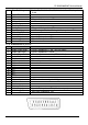
CP-520/520A/520F Service Manual 1.2 CHANNEL/FREQUENCY TABLE CHANNEL C01 C02 C03 C04 C05 C06 C07 C08 C09 C10 C11 C12 C13 C14 C15 C16 C17 C18 C19 C20 C21 C22 C23 C24 C25 C26 C27 C28 C29 C30 C31 C32 C33 C34 C35 C36 C37 C38 C39 C40 C41 C42 C43 C44 C45 EUROPE CCIR 46.25 48.25 55.25 62.25 175.25 182.25 189.25 196.25 203.25 210.25 217.25 224.25 53.75 82.25 183.75 192.25 201.25 471.25 479.25 487.25 495.25 503.25 511.25 519.25 527.25 535.25 543.25 551.25 559.25 567.25 575.25 583.25 591.25 599.25 607.25 615.
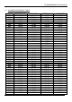
CP-520/520A/520F Service Manual C46 C47 C48 C49 C50 C51 C52 C53 C54 C55 C56 C57 C58 C59 C60 C61 C62 C63 C64 C65 C66 C67 C68 C69 C70 C71 C72 C73 C74 C75 C76 C77 S01 S02 S03 S04 S05 S06 S07 S08 S09 S10 S11 S12 S13 S14 S15 S16 S17 DTV R&D Europe 671.25 679.25 687.25 695.25 703.25 711.25 719.25 727.25 735.25 743.25 751.25 759.25 767.25 775.25 783.25 791.25 799.25 807.25 815.25 823.25 831.25 839.25 847.25 855.25 863.25 69.25 76.25 83.25 90.25 97.25 59.25 93.25 105.25 112.25 119.25 126.25 133.25 140.25 147.
CP-520/520A/520F Service Manual S18 S19 S20 S21 S22 S23 S24 S25 S26 S27 S28 S29 S30 S31 S32 S33 S34 S35 S36 S37 S38 S39 S40 S41 DTV R&D Europe 280.25 287.25 294.25 303.25 311.25 319.25 327.25 335.25 343.25 351.25 359.25 367.25 375.25 383.25 391.25 399.25 407.25 415.25 423.25 431.25 439.25 447.25 455.25 463.25 136.00 160.00 303.25 311.25 319.25 327.25 335.25 343.25 351.25 359.25 367.25 375.25 383.25 391.25 399.25 407.25 415.25 423.25 431.25 439.25 447.25 455.25 463.25 295.25 303.25 311.25 319.25 327.
CP-520/520A/520F Service Manual 2 SAFETY INSTRUCTION WARNING: Only competent service personnel may carry out work involving the testing or repair of this equipment. X-RAY RADIATION PRECAUTION 1. Excessive high voltage can produce potentially hazardous X-RAY RADIATION. To avoid such hazards, the high voltage must not exceed the specified limit. The nominal value of the high voltage of this receiver is 25-26 KV (20”-21”) or 26 KV (25” - 28”) at max beam current.
CP-520/520A/520F Service Manual 3 3.1 ALIGNMENT INSTRUCTIONS MICROCONTROLLER CONFIGURATION : SERVICE MODE To switch the TV set into service mode please see instruction below. 1 - Select PR. number 91 2 - Adjust sharpness to minimum and exit all menus. 3 – Within 2 seconds press the key sequence : RED - GREEN - menu The software version is displayed beside the word Service, e.g. “SERVICE VER 00.05”. To exit SERVICE menu press menu key or Std By key. 3.
CP-520/520A/520F Service Manual 3.4 OPTION 1 B7 TOP 1 Teletext OFF TOP 0 Teletext ON 3.
CP-520/520A/520F Service Manual 3.6 NVM default setting The purpose of this message, when you change a virgin EEPROM, is to allow to modify the NVM DATA to desired values. 1 - Introduction : The NVM default valus are fixed for the user, but for flexibility in service, these data are stored in NVM and can be changed when the TV set is in a special mode call "NVM EDITOR". This mode can only be access from "FACTORY" mode. 2 - Entering into "FACTORY" mode.
CP-520/520A/520F Service Manual NVM DATA CHANGE LIST No Register Name Address (hex) Default 28A8 CP-520 2880 21U7 CP-520F 2881 29U7 CP-520A 21Y1 20T2 1 OCP_THRESHOLD 0x58F 0x91 <- <- <- <- <- <- <- 2 DCXO 0x590 0x4E <- <- <- <- <- <- <- 3 AGC_PHILIPS 0x5C1 0xAB <- <- <- <- <- <- <- 4 AGC_NC 0x5C2 0xAB <- <- <- <- <- <- <- 5 AGC_ALPS 0x5C3 0xB6 <- <- <- <- <- <- <- 6 AGC_PARTSNIC 0x5C4 0xB6 <- <- <- <- <- <- <- 7 AGC_PHILIPS_START
CP-520/520A/520F Service Manual 3.7 TV SET ALIGNMENT 3.7.1 G2 ALIGNMENT - Tune a colour bar pattern. - Find the “G2 – SCREEN” item in service mode. - Adjust screen volume (on FBT) to bring the cursor to central position(Green). 3.7.2 WHITE BALANCE - Select a dark picture and adjust RED BIAS and GRN BIAS to the desired colour temperature. - Select a bright picture and adjust RED, GRN and BLUE GAIN to the desired colour temperature. 3.7.
CP-520/520A/520F Service Manual HOR WIDTH adjust for 93% overscan. PARABOLA CORNER B & CORNER T EW TRAPEZ 3.7.7 AGC - Make sure option bits are correct for the tuner fitted on the chassis (See above how to change option bits). - Adjust the antenna signal level at 62 dBµV - Tune a colour bar pattern. - Find the “AGC” item in service mode. - Press the key “OK” on the remote keypad and wait until AGC level stabilise to the optimum value.
CP-520/520A/520F Service Manual 4 IC DESCRIPTION 4.1 UOC III Series The UOCIII series combines the functions of a Video Signal Processor (VSP) together with a FLASH embedded TEXT/Control/Graphics µ-Controller (TCG µ-Controller) and US Closed Caption decoder.
CP-520/520A/520F Service Manual 4.1.2.
CP-520/520A/520F Service Manual 4.1.3. PINNING QFP 128pin 1 2 3 4 5 6 7 8 9 10 11 12 13 14 15 16 17 18 Symbol P1.5/TX P1.4/RX P1.2/INT2 VSSC3 VDDC3 P2.5/PWM4 P2.4/PWM3 VSSC/P P3.3/ADC3 P3.2/ADC2 DECV1V8 VDDC1 P3.1/ADC1 P3.0/ADC0 P2.3/PWM2 P2.2/PWM1 P2.1/PWM0 P2.0/TPWM 19 VDDP(3.3V) 20 21 22 23 24 25 26 27 28 29 30 31 P1.7/SDA P1.6/SCL P1.3/T1 P0.0/I2SDI1/O P0.1/I2SDO1 P0.2/I2SDO2 P0.3/I2SCLK P0.4/I2SWS VSSC2 VDDC2 P1.1/T0 P1.0/INT1 32 INT0/P0.5 33 34 35 36 37 38 39 40 VDDadc(1.8) VSSadc VDDA2(3.
CP-520/520A/520F Service Manual 43 44 45 46 47 48 49 50 51 52 53 54 55 56 57 58 59 60 61 62 63 64 65 66 67 68 69 70 71 72 73 74 75 76 77 78 79 80 81 82 83 84 85 86 Green output Red output black current input beam current limiter input 3rd supply for TV processor ground 3 for TV-processor 3rd B input / PB input 3rd G input / Y input 3rd R input / PR input 3rd RGB / YPBPR insertion input V-output for YUV interface (general purpose switch VOUT(SWO1) output) U-output for YUV interface (2nd RGB / YPBPR UOUT(INS
CP-520/520A/520F Service Manual 87 SIFAGC/DVBAGC (2) 88 89 PLLIF GND2 90 QSSO/AMOUT/AUDEE M (2) 91 92 93 94 95 DECSDEM AUDOUTSR AUDOUTSL AUDIOIN5R AUDIOIN5L 96 AVL/SWO/SSIF/ REFO/REFIN (2) 97 98 99 100 101 102 103 104 105 106 107 108 109 110 111 112 113 114 115 EHTO AGCOUT SIFIN2/DVBIN2 (2) SIFIN1/DVBIN1 (2) GNDIF IREF VSC VIFIN2 VIFIN1 VDRA VDRB EWD/AVL (1) DECBG SECPLL GND1 PH1LF PH2LF VP1 DECDIG 116 VGUARD/SWIO 117 VSSA1 118 XTALOUT 119 XTALIN 120 VREF_POS_HPR 121 VREF_NEG_HPL+HPR 122 VREF_
CP-520/520A/520F Service Manual 4.1.4 FEATURES Analogue Video Processing (all versions) · Multi-standard vision IF circuit with alignment-free PLL demodulator · Internal (switchable) time-constant for the IF-AGC circuit · Switchable group delay correction and sound trap (with switchable centre frequency) for the demodulated CVBS signal · DVB/VSB IF circuit for preprocessing of digital TV signals. · Video switch with 3 external CVBS inputs and a CVBS output.
CP-520/520A/520F Service Manual windows in parallel. · Linear and non-linear horizontal scaling of the video signal to be displayed. Sound Demodulation (all versions) · Separate SIF (Sound IF) input for single reference QSS (Quasi Split Sound) demodulation. · AM demodulator without extra reference circuit · The mono intercarrier sound circuit has a selective FM-PLL demodulator which can be switched to the different FM sound frequencies (4.5/5.5/6.0/6.5 MHz).
CP-520/520A/520F Service Manual · FM overmodulation adaptation option to avoid clipping and distortion Audio Multi Channel Decoder (stereo versions with Audio DSP) · Dolby® Pro Logic® (DPL) (1) · Five channel processing for Main Left and Right, Subwoofer, Centre and Surround. To exploit this feature an external DAC is required.
CP-520/520A/520F Service Manual · 5 PWM (6-bits) outputs for analogue control functions · Remote Control Pre-processor (RCP) · Universal Asynchronous Receiver Transmitter (UART) Data Capture · Text memory up to 10 pages · Inventory of transmitted Teletext pages stored in the Transmitted Page Table (TPT) and Subtitle Page Table (SPT) · Data Capture for US Closed Caption · Data Capture for 525/625 line WST, VPS (PDC system A) and Wide Screen Signalling (WSS) bit decoding · Automatic selection between 525 WST/
CP-520/520A/520F Service Manual all-NPN output stage and standby/mute logic. The TDA8946J comes in a 17-pin DIL-bentSIL(DBS) power package. 4.2.1 FEATURES § § § § § § § § Few external components Fixed gain Standby and mute mode No on/off switching plops Low standby current High supply voltage ripple rejection Outputs short-circuit protected to ground, supply and across the load Thermally protected Pin description Pin 1 2 3 4 5 6 7 8 9 10 11 12 Symbol OUT1GND1 Vcc1 OUT1+ n.c. IN1+ n.c.
CP-520/520A/520F Service Manual Block diagram TDA8946J DTV R&D Europe 26
CP-520/520A/520F Service Manual 4.3 TDA8358J VERTICAL AMPLIFIER The TDA8358J are power circuit for use in 90° and 110° colour deflection systems for field frequencies of 25 to 200Hz field frequencies, and for 4:3 and 16/9 picture tubes. The IC contains a vertical deflection output circuit, operating as a high efficiency class G system. The full bridge output circuit allows DC coupling of the deflection coil in combination with single positive supply voltages.
CP-520/520A/520F Service Manual Pinning Pin 1 2 3 4 5 6 7 8 9 10 11 12 13 Symbol INA INB VP OUTB INEW VGND EWGND OUTEW VFB OUTA GUARD FEEDB COMP Description Positeve vertical input Negative vertical input Supply voltage Vertical output voltage B East-west input voltage Vertical ground East-west ground East-west output voltage Flyback supply voltage Vertical output voltage A Guard output voltage Input measuring resistor Input compensation current Block diagram TDA8358J DTV R&D Europe 28
CP-520/520A/520F Service Manual 4.4 TDA6107AJF The TDA6107AJF includes three video output amplifiers and is intended to drive the three cathodes of a colour CRT directly. The device is contained in a plastic DIL-bent-SIL 9-pin medium power(DBS9MPF) package, and uses high-voltage DMOS technology. To obtain maximum performance, the amplifier should be used with black-current control. 4.4.1 Features § § § § § § § § § § Typical bandwidth of 5.
CP-520/520A/520F Service Manual Block diagram TDA6107AJF 4.5 24WC16 - 16 KB EEPROM Features : § 16 Kbit serial I2C bus EEPROM § 400KHz I2C Bus Compatible § supply voltage : 1.8 V to 6.0 V § Low Power CMOS Technology § 1 Million Erase/Write cycles (minimum) § 100 year data retention (minimum) Pin description Pin No.
CP-520/520A/520F Service Manual 4.6 STR - F6653 4.6.1 GENERAL DESCRIPTION The STR-F6653 is an hybrid IC with a build-in MOSFET and control IC, designed for flyback converter type switch mode power supply applications. 4.6.2 FEATURES § § Small SIP fully isolated moulded 5 pins package Many protection functions : v Pulse-by-pulse overcurrent protection (OCP) v Overvoltage protection with latch mode (OVP) v Thermal protection with latch mode (TSD) 4.6.
CP-520/520A/520F Service Manual 4.6.4 PIN DESCRIPTION PIN NAME 1 Overcurrent feedback 2 3 4 5 Source Drain Supply Ground SYMBOL O.C. P/E.B. S D VIN GND DESCRIPTION Input of over current detection signal and feedback signal Mosfet source Mosfet drain Input of power supply for control circuit Ground 4.6.5 CONTROL PART - ELECTRICAL CHARACTERISTICS DESCRIPTION Operation start voltage Operation stop voltage Circuit current in operation Circ.
CP-520/520A/520F Service Manual 4.6.6 MOSFET ELECTRICAL CHARACTERISTICS DESCRIPTION Drain-to-source break down voltage Drain leakage current On-resistance Switching time Thermal resistance DTV R&D Europe IC PIN NUMBER SYMBOL 3-2 VDSS 3-2 3-2 3-2 - IDSS RDS (on) tf OCH - F MIN. 650 RATING TYPE - MAX - UNIT V - - 300 1.95 250 0.
CP-520/520A/520F Service Manual 5 5.
CP-520/520A/520F Service Manual 5.2 FUNCTIONAL DESCRIPTION OF VIDEO PROCESSOR 5.2.1 Vision IF amplifier The vision IF amplifier can demodulate signals with positive and megative modulation. The PLL demodulator is completely alignment-free. The VCO of the PLL circuit is internal and the grequency is fixed to the required value by using the clock ftequency of the TCG u-Controller as a reference. The setting of the various frequencies (e.g. 38, 38.9, 45.75 and 58.
CP-520/520A/520F Service Manual applied to obtain sufficient selectivity (the sound input can be activated by means of the setting of CMB2-CMB0 bits in subaddress 4AH). The setting to the wanted frequency is realised by means of the control bits FMA, FMB and FMC in the control bit 33H. From the output status bytes it can be read whether the PL Lfrequency is inside or outside the window and whether thePLL is in lock or not.
CP-520/520A/520F Service Manual The Ics have 3 inputs for external CVBS signals. All CVBS inputs can be used as Y input for the insertion of Y/C signals.However, the CVBS(Y)2 input has to be combined with the C3 input. It is possible to add and extra CVBS(Y/C) input via the pins which are intended to be used for YUV interface (or RGB/YPrPb input). The selection of this additional CVBS(Y/C) input is made via the YC bit. The function of the IFVO/SVO/CVBSI pin is determined by the SVO1/SVO0 bits.
CP-520/520A/520F Service Manual available on one of the other CVBS inputs.In this condition the connections between the vision IF amplifier and the synchronisation circuit can be switched on and off by means of the VDX bit. The VDXEN bit must be set to “1” for this mode. The vertical synchronisation is realised by means of a divider circuit. 5.2.7 Horizontal and vertical drive The horizontal drive is switched on and off via the soft start/stop procedure.
CP-520/520A/520F Service Manual The circuit contains the following picture improvement features: n Peaking control circuit. The peaking function can be activated for all incoming CVBS, Y/C and RGB/YPrPb signals. Various parameters of the peaking circuit can be adapted by means of the I2C-bus. The main parameters are: n n n n n n Peaking centre frequency (via the PF1/PF0 bits in subaddress 19H). Ratio of positive and negative peaks (via the RPO1/RPO0 bits in subaddress 47H).
CP-520/520A/520F Service Manual The SECAM decoder contains an auto-calibrating PLL demodulator which has two references, viz: the divided reference frequency (obtained from the-Controller) which is used to tune the PLL to the desired free-running frequency and the bandgap reference to obtain the correct absolute value of the output signal. The VCO of the PLL is calibrated during each vertical blanking period, when the IC is in search or SECAM mode.
CP-520/520A/520F Service Manual WPR(GB) CL CCC-gain R(GB)-gain ‘0’ ‘0’ B6 B6 B5 B3 B5 B5 B4 B2 B4 B4 B3 B1 B3 B3 B2 B0 B2 B2 B1 ‘0’ B1 B1 B0 ‘0’ B0 B0 Max 64 Max 60 Max 126 Max 126 The setting of the gain registers of the 3 channels can be stored during switch off and can be loaded again during switch-on so that the drive conditions are maintained. When required the operation of the CCC system can be changed into a one-point black current system.
CP-520/520A/520F Service Manual 5.2.11 I2C-BUS USER INTERFACE DESCRIPTION The UOC III series is fully controlled via the I2C-bus. Control is exercised by writing data to one or more internal registers. Status information can be read from a set of info registers to enable the controlling microcontroller determine whether any action is required. The device has an I2Cbus slave transceiver, in accordance with the fast-mode specification, with a maximum speed of 400 kbits/s.
CP-520/520A/520F Service Manual n Automatic decoder configuration and signal routing depending on the selected or detected standard n FM overmodulation adaptation option to avoid clipping and distortion 5.3.1 Supported standards The multistandard capability of the TV Sound Processor covers all terrestrial TV sound standards, FM Radio and satellite FM. The AM sound of L/L' standard is normally demodulated in the 1st sound IF.
CP-520/520A/520F Service Manual PARAMETER Pilot frequency Stereo identification frequency Dual indetification frequency AM modulation depth A2/A2* 54.6875kHz = 3.5 x line freq. 117.5 Hz = line freq / 133 274.1 Hz = line freq / 57 50% A2+ (KOREA) 55.0699 kHz = 3.5 x line freq. 149.9 Hz = line freq / 105 276.0 Hz = line freq / 57 50% 2-CARRIERSYSTEMSWITHNICAM [Table] NICAM standards SC1 STANDARD FREQUENCY (MHz) TYPE B/G I D/K L 5.5 6.0 6.5 6.5 FM FM FM AM MODULATION DEVIATION (kHz) INDEX(%) NOM./MAX.
CP-520/520A/520F Service Manual intercarrier and an external second SIF(2NDSIFEXT), e.g. an intercarrier coming from a PIP frontend. In other applications a 10.7MHz radio IF or satellite FM may be connected to this input. The selected SSIF passes some anti alias filtering, is amplified in an AGC amplifier (SSIF AGC) and is then converted from analogue to digital (SSIF ADC). The audio signal out of the AM demodulator is connected to the analogue crossbar at the video processor.
CP-520/520A/520F Service Manual decoding is done in the DEMDEC block of the Sound DSP. The DEMDEC processing will be described in the next chapter. The audio signals (AUD ADC IN) from the analogue crossbar pass the audio ADC and are fed directly into the AUDIO part of the Sound DSP like the I2S signals, which is coming from I2S processing hardware. After level adjust all signals from the DEMDEC and the I2S input are available at the digital input crossbar.
CP-520/520A/520F Service Manual output signal of the first demodulator can be used for further demodulation of multiplex signals used in the BTSC, EIAJ and FM Radio standards. FMIDENTIFICATION The identification of the FM sound mode is performed by AM synchronous demodulation of the pilot signal and narrow-band detection of the identification frequencies. The result is available via the control bus interface.
CP-520/520A/520F Service Manual number of sound sample errors, resulting from parity checking, that occurred in the past 128ms period. The Bit Error Rate (BER) can be calculated using the following equation; During NICAM mode a switchable J17 de-emphasis is supplied. NICAM AUTO-MUTE If the Auto Standard Detection (ASD) or the Static Standard Detection (SSS) feature is activated the following auto mute function is in effect.
CP-520/520A/520F Service Manual 6. SERVICE PARTS LIST Caution : In this Service Manual, some parts can be changed for improving, their performance without notice in the parts list. So, if you need the latest parts information, please refer to PPL(Parts Price List) in Service Information Center(http://svc.dwe.co.kr) 6.
CP-520/520A/520F Service Manual z_loc z_parts_code Z101 Z102 ZZ200 E01 E02 E03 E04 E05 E06 E07 E08 E09 E10 E13 E14 E15 E16 E17 E18 E19 E20 E21 E22 E23 E24 E25 E26 E27 E28 E29 E30 E31 E32 E33 E34 E35 E36 E37 E38 E39 E40 E41 E42 E43 E44 E45 E46 E47 E48 E49 E50 E51 E52 E53 E54 E55 E56 E57 ZZ200 I501 ZZ200 C102 C104 C106 C121 C122 C305 C313 C320 C350 C351 C370 C401 C412 C414 C418 C420 C421 C501 C502 C505 5PK3953M— 5PK9650M— PTMPJBY28A8FF 4856310600 4856310600 4856310600 4856310600 4856310600 4856310600 4856310
CP-520/520A/520F Service Manual z_loc z_parts_code C901 C968 CA10 F801A F801B L517 L518 L519 Q120 Q402 Q501 Q502 Q503 Q504 Q506 Q507 Q508 Q513 Q514 Q515 Q601 Q602 Q807 Q808 Q809 Q810 Q811 Q813 Q814 Q815 Q816 R415 SW700 SW701 SW702 SW703 SW704 Z601 Z602 Z603 Z604 Z605 Z606 Z607 Z608 Z609 Z610 Z611 Z612 ZZ200 20 10 A001 C103 C107 C108 C120 C123 C503 C504 C512 C523 C530 C531 C532 C533 C541 C544 C546 C550 C551 C555 C557 C564 C565 C566 C571 C572 C573 C575 CCXB1H561K CMXL2E104K CCXB1H102K 4857415001 4857415001 5
CP-520/520A/520F Service Manual z_loc z_parts_code J106 J107 J108 J109 J11 J111 J112 J113 J114 J12 J13 J14 J15 J16 J17 J18 J19 J20 J21 J22 J23 J24 J25 J26 J31 J32 J33 J35 J36 J37 J39 J4 J40 J41 J42 J43 J44 J45 J46 J47 J48 J49 J50 J51 J52 J53 J54 J56 J57 J58 J59 J60 J61 J62 J63 J64 J65 J66 J67 J68 J69 J7 J70 J71 J72 J73 J74 J76 J78 J80 J81 J82 J83 J84 J86 J87 J88 J89 J90 J91 J92 85801065GY 85801065GY 85801065GY 85801065GY 85801065GY 85801065GY 85801065GY 85801065GY 85801065GY 85801065GY 85801065GY 85801065G
CP-520/520A/520F Service Manual z_loc z_parts_code R540 R541 R542 R543 R544 R545 R546 R547 R551 R552 R553 R554 R555 R556 R557 R558 R559 R560 R561 R562 R563 R564 R565 R566 R567 R568 R569 R571 R572 R573 R574 R575 R576 R577 R578 R579 R580 R581 R582 R583 R584 R585 R586 R587 R588 R589 R590 R598 R599 R601 R602 R608 R609 R610 R611 R612 R650 R660 R661 R662 R700 R713 R720 R721 R722 R723 R724 R805 R806 R807 R808 R810 R811 R812 R813 R814 R815 R816 R817 R820 R821 RD-AZ471JRN-AZ3902F RD-AZ682JRD-AZ222JRD-AZ222JRD-AZ473
CP-520/520A/520F Service Manual 6.
CP-520/520A/520F Service Manual z_loc z_parts_code E30 E31 E32 E33 E34 E35 E36 E37 E38 E42 E43 E44 E47 E48 E49 E50 E51 E54 E55 E56 E57 ZZ200 I501 ZZ200 C102 C104 C106 C121 C122 C305 C313 C320 C350 C351 C370 C401 C412 C414 C418 C420 C421 C501 C502 C505 C507 C508 C509 C510 C511 C513 C514 C515 C516 C517 C518 C519 C520 C521 C522 C524 C525 C526 C527 C528 C529 C534 C535 C536 C537 C538 C539 C540 C542 C543 C545 C547 C548 4856310300 4856310300 4856310300 4856310300 4856310300 4856310300 4856310300 4856310300 485631
CP-520/520A/520F Service Manual z_loc z_parts_code Q815 Q816 SW700 SW701 SW702 SW703 SW704 Z601 Z602 Z603 Z604 Z605 Z606 Z607 Z608 Z609 Z610 Z611 Z612 ZZ200 20 10 A001 C103 C107 C108 C120 C123 C503 C504 C512 C523 C530 C531 C532 C533 C541 C544 C546 C550 C551 C555 C557 C564 C565 C566 C571 C572 C573 C575 C578 C589 C590 C591 C592 C701 C830 CA01 CA02 CA03 CA04 CA05 CA06 CA28 D101 D102 D313 D405 D407 D408 D410 D414 D450 D501 D502 D503 D504 D520 D521 D522 D523 T2SA1980YT2SC5343Y5S50101090 5S50101090 5S50101090 5S
CP-520/520A/520F Service Manual z_loc z_parts_code J39 J4 J40 J41 J42 J43 J44 J45 J46 J47 J48 J49 J5 J50 J500 J51 J52 J54 J56 J57 J58 J59 J6 J60 J61 J62 J63 J64 J65 J66 J67 J68 J69 J7 J70 J71 J72 J73 J74 J76 J78 J80 J800 J81 J82 J83 J84 J86 J87 J88 J89 J90 J91 J92 J94 J95 J96 J97 J98 J99 L101 L350 L351 L505 L506 L507 L508 L509 L510 L512 L513 L515 L516 L523 L650 L801 R103 85801065GY 85801065GY 85801065GY 85801065GY 85801065GY 85801065GY 85801065GY 85801065GY 85801065GY 85801065GY 85801065GY 85801065GY 85801
CP-520/520A/520F Service Manual z_loc z_parts_code R571 R572 R573 R574 R575 R576 R577 R578 R579 R580 R581 R582 R583 R584 R585 R586 R587 R588 R589 R590 R598 R599 R601 R602 R608 R609 R610 R611 R612 R650 R660 R661 R662 R700 R701 R702 R713 R720 R721 R722 R723 R724 R805 R806 R807 R808 R810 R811 R812 R813 R814 R815 R816 R817 R820 R821 R823 R829 R830 R840 R841 R842 R850 R870 R901 R910 R911 R912 R913 R914 R915 R921 R922 R923 R996 R997 RA02 RA03 RA04 RA05 RA06 RD-AZ102JRD-AZ103JRD-AZ103JRD-AZ103JRD-AZ103JRD-AZ102JR
CP-520/520A/520F Service Manual 6.
CP-520/520A/520F Service Manual z_loc z_parts_code E33 E34 E35 E36 E37 E38 E42 E43 E44 E47 E48 E49 E50 E51 E54 E55 E56 E57 ZZ200 I501 ZZ200 C102 C104 C106 C121 C122 C305 C313 C320 C350 C351 C370 C401 C412 C414 C418 C420 C421 C501 C502 C505 C507 C508 C509 C510 C511 C513 C514 C515 C516 C517 C518 C519 C520 C521 C522 C524 C525 C526 C527 C528 C529 C534 C535 C536 C537 C538 C539 C540 C542 C543 C545 C547 C548 C549 C552 C553 C554 C556 C558 C560 4856310300 4856310300 4856310300 4856310300 4856310300 4856310300 48563
CP-520/520A/520F Service Manual z_loc z_parts_code Z605 Z606 Z607 Z608 Z609 Z610 Z611 Z612 ZZ200 20 10 A001 C103 C107 C108 C120 C123 C503 C504 C512 C523 C530 C531 C532 C533 C541 C544 C546 C550 C551 C555 C557 C564 C565 C566 C571 C572 C573 C575 C578 C589 C590 C591 C592 C701 C830 CA01 CA02 CA03 CA04 CA05 CA06 CA28 D101 D102 D313 D405 D407 D408 D410 D414 D450 D501 D502 D503 D504 D520 D521 D522 D523 D601 D602 D710 D801 D802 D803 D804 D805 D806 D808 D809 5PEFST471Y 5PEFST471Y 5PEFST471Y 5PEFST471Y 5PEFST471Y 5PE
CP-520/520A/520F Service Manual z_loc z_parts_code J49 J5 J50 J500 J51 J52 J54 J56 J57 J58 J59 J6 J60 J61 J62 J63 J64 J65 J66 J67 J68 J69 J7 J70 J71 J72 J73 J74 J76 J78 J80 J800 J81 J82 J83 J84 J86 J87 J88 J89 J90 J91 J92 J94 J95 J96 J97 J98 J99 L101 L350 L351 L505 L506 L507 L508 L509 L510 L512 L513 L515 L516 L523 L650 L801 R103 R104 R105 R106 R107 R114 R115 R120 R131 R310 R311 R331 R340 R350 R351 85801065GY 85801065GY RD-AZ101J85801065GY 85801065GY 85801065GY 85801065GY 85801065GY 85801065GY 85801065GY 85
CP-520/520A/520F Service Manual z_loc z_parts_code R584 R585 R586 R587 R588 R589 R590 R598 R599 R601 R602 R608 R609 R610 R611 R612 R650 R660 R661 R662 R700 R701 R702 R713 R720 R721 R722 R723 R724 R805 R806 R807 R808 R810 R811 R812 R813 R814 R815 R816 R817 R820 R821 R823 R829 R830 R840 R841 R842 R850 R870 R901 R910 R911 R912 R913 R914 R915 R921 R922 R923 R996 R997 RA02 RA03 RA04 RA05 RA06 RA07 RA08 RA09 RA10 RA11 RA12 RA13 RA14 RA15 RA16 RA17 RA18 RA19 RD-AZ101JRD-AZ101JRD-AZ101JRD-AZ101JRD-AZ102JRD-AZ102JR
CP-520/520A/520F Service Manual 6.
CP-520/520A/520F Service Manual z_loc z_parts_code E18 E19 E20 E21 E22 E23 E24 E25 E26 E27 E28 E29 E30 E31 E32 E33 E34 E35 E36 E37 E38 E39 E40 E41 E42 E43 E44 E45 E46 E47 E48 E49 E50 E51 E52 E53 E54 E55 E56 E57 ZZ200 I501 ZZ200 C102 C104 C106 C121 C122 C305 C313 C320 C350 C351 C370 C401 C412 C414 C418 C420 C421 C501 C502 C505 C507 C508 C509 C510 C511 C513 C514 C515 C516 C517 C518 C519 C520 C521 4856310600 4856310600 4856310600 4856310300 4856310300 4856310300 4856310300 4856310300 4856310300 4856310300 485
CP-520/520A/520F Service Manual z_loc z_parts_code Q504 Q506 Q507 Q508 Q513 Q514 Q515 Q601 Q602 Q807 Q808 Q809 Q810 Q811 Q813 Q814 Q815 Q816 R415 SW700 SW701 SW702 SW703 SW704 Z601 Z602 Z603 Z604 Z605 Z606 Z607 Z608 Z609 Z610 Z611 Z612 ZZ200 20 10 A001 C103 C107 C108 C120 C123 C503 C504 C512 C523 C530 C531 C532 C533 C541 C544 C546 C550 C551 C555 C557 C564 C565 C566 C571 C572 C573 C575 C578 C589 C590 C591 C592 C701 C830 CA01 CA02 CA03 CA04 CA05 CA06 CA28 T2SA1980YT2SC5343YT2SA1980YT2SC5343YT2SA1980YTH2N7000
CP-520/520A/520F Service Manual z_loc z_parts_code J17 J18 J19 J20 J21 J22 J23 J24 J25 J26 J31 J32 J33 J35 J36 J37 J38 J39 J4 J40 J41 J42 J43 J44 J45 J46 J47 J48 J49 J50 J500 J51 J52 J53 J54 J56 J57 J58 J59 J60 J61 J62 J63 J64 J65 J66 J67 J68 J69 J7 J70 J71 J72 J73 J74 J76 J78 J80 J81 J82 J83 J84 J86 J87 J88 J89 J90 J91 J92 J93 J94 J95 J96 J97 J98 J99 L101 85801065GY 85801065GY 85801065GY 85801065GY 85801065GY 85801065GY 85801065GY 85801065GY RD-AZ101JRD-AZ101J85801065GY 85801065GY 85801065GY 85801065GY 85
CP-520/520A/520F Service Manual z_loc z_parts_code R544 R545 R546 R547 R551 R552 R553 R554 R555 R556 R557 R558 R559 R560 R561 R562 R563 R564 R565 R566 R567 R568 R569 R571 R572 R573 R574 R575 R576 R577 R578 R579 R580 R581 R582 R583 R584 R585 R586 R587 R588 R589 R590 R598 R599 R601 R602 R608 R609 R610 R611 R612 R650 R660 R661 R662 R700 R701 R702 R713 R720 R721 R722 R723 R724 R805 R806 R807 R808 R810 R811 R812 R813 R814 R815 R816 R817 RD-AZ222JRD-AZ473JRD-AZ181JRD-AZ563JRD-AZ823JRD-AZ103JRD-AZ103JRD-AZ103JRD-
7.
7.
7.
7.
7.
7.
7.
7.
7.
8.
8.
8.
9.
9.
9.