S/M No. : DWC121R040 Service Manual Window Type Room Air Conditioner Model: DWC-121R / (DWC-124R) DWA-122R / (DWA-124R) DWB-122R / (DWB-124R) DWA-121R / DWB-121R DWB-123R / DWA-150R DWA-151R / (DWA-152R) ✔ Caution : In this Manual, some parts can be changed for improving, their performance without notice in the parts list. So, if you need the latest parts information,please refer to PPL(Parts Price List) in Service Information Center (http://svc.dwe.co.kr). DAEWOO ELECTRONICS CO., LTD.
Contents CONTENTS 1. Specifications ................................................................................................2 2. Operation .....................................................................................................3 3. Wiring Diagram..........................................................................................12 4. Refrigerant Cycle .........................................................................................13 5. Control Block Diagram..............
1. SPECIFICATIONS MODEL ITEM DWC-121R (DWC-124R) DWA-121R DWA-122R (DWA-124R) DWB-121R Function DWB-122R (DWB-124R) DWB-123R DWA-150R DWA-151R (DWA-152R) Cooling only Power source AC 115V, 60Hz AC 208~230V, 60Hz AC 220~240V, 50Hz AC 220~230V, 50Hz AC 240V, 50Hz AC 208~230V, 60Hz Btu/h 12,100 12,000 12,000 11,700 12,000 11,500 14,018 14,000 Kcal/h 3,050 3,024 3,024 2,950 3,024 2,898 3,533 3,528 10.1 10.2 10.1 9.9 10.0 10.0 9.4 9.8 2.55 2.57 2.55 2.49 2.52 2.
2.
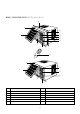
● DW*-124R/DWA-152R (NOTE:* ➔ A or B or C) 0 3 q 7 2 4 w Roo 8 m Air-c ondi tione r 1 5 9 6 3 7 2 4 Roo 8 m Air-c ondi tione r 1 5 9 NO PART NAME NO 1 AIR FILTER 7 BLADE HORIZENTAL 2 GRILLE 8 AIR VENT 3 CABINET 9 FRAME GRILLE 4 BLADE VERTICAL 10 FRAME GUIDE TOP 5 PANEL CONTROL 11 FRAME WINDOW KIT 6 REMOTE CONTROLLER 12 SHUTTER WINDOW 4 PART NAME
2 REMOTE CONTROLLER REMOCON SIGNAL TRANSMITTER TIMER/CANCEL • Everytime you push this button, timer is set as follow. (1Hr→2Hr→3Hr→4Hr→5Hr→6Hr→8 Hr→10Hr→12Hr→16Hr→20Hr→24Hr →CANCEL). After the unit is timed, if this button is pushed, timer is canceled. TIMER/ CANCEL FAN SPEED SLEEP • SLEEP mode is selected as follow. (L1→L2→Cancel) SLEEP AUTO SWING FAN SPEED • Everytime you push this button, it is selected as follow.
3 REMOTE CONTROLLER DISPLAY ● SELECT ONE ALTERNATIVE PAGE 6 or PAGE 7 MODE DISPLAY • It displays the operating mode. TEMP./TIMER DISPLAY • It displays the temperature and the timer. REMOCON SIGNAL RECEIVER TEMPERATURE SET BUTTON • It is the button to set the desired room temperature.
MODE DISPLAY • It displays the operating mode. TEMP./TIMER DISPLAY • It displays the temperature and the timer. REMOTE SIGNAL RECEIVER TEMPERATURE SET • It is the button to set the desired room temperature. The temperature can be set within a range from 16°C (60°F) to 32°C (90°F) by 1°C (1°F) SENSOR Room Air-conditioner Fan Room temp Turbo Desired temp Cooling Timer MODE TEMP FAN SPEED AUTO SWING FAN SPEED • Everytime you push this button, It is selected as follow.
Replacing Batteries 1 Remove the COVER from the back of the remote controller. • Slide the cover according to the arrow direction 2 Insert two battaries. • Be sure that the (+) and (–) directions are correct • Be sure that both batteries are new – + 3 Re-attach the cover. • Slide it back into position + – • Do not use rechargeable batteries such batteries differ from standard dry cells in shape, dimensions and performance.
4 DESCRIPTION OF FUNCTIONS OFF-Timer If you set time in OFF-Timer Mode, the unit will stop at the set time. ON Unit ON Unit OFF OFF SET Time HOUR ON-Timer If you set time in ON-Timer Mode, the unit will run at the set time.
Fan Speed (1) Motor speed (high speed, normal speed, low speed). (2) Remote controller setting fan speed. (H, M, L) (3) Relation of operating mode between fan speed. FAN ONLY COOL TURBO H H H H M M M - L L L - Sleep Mode (1) When you are going to sleep, select sleep button in remocon and the unit controls the room to the desired temperature. (The unit will not operate after 4 hour) (2) For changing the temperature.
Auto Swing (1) When you push this button, in remocon the left/right flap move to the position of keeping the room temperature comiortable. (2) The air discharge direction procedure is below. Auto swing Fixed Turbo Mode(Powerful Cooling) (1) Cooling Condition 1 Fan Speed: High speed 2 Set temperature:16˚C(Fixed) 3 Compressor and Fan ON OFF (Room temperature-18˚C) -1 0 1 Self-Diagnostic Function The control will contain diagnostic test to verify the integrity of the system.
3.
4. REFRIGERANT CYCLE Evaporator Blower fan M Accumulator Capillary tube MOTOR Compressor Propeller fan Condenser Model Name DWA-121R Contents Capillary tube Charge Quantity DWA-122R (DWA-124R) ID1.6Ø x L800 740g DWB-121R DWB-122R DWC-121R (DWB-124R) (DWC-124R) ID1.6Ø x L900 790g DWB-123R ID1.6Ø x L800 730g 690g 13 680g 760g DWA-150R DWA-151R (DWA-152R) ID1.
5.
6.
Part List ● MAIN PCB ASS’Y(3104302300) NO PART NAME SPEC PART CODE Q’TY REMARK 1 2 3 4 5 6 7 8 9 10 11 12 13 14 15 16 17 18 19 20 21 22 23 24 25 26 27 28 29 30 31 32 33 34 35 36 37 38 39 40 41 IC MICOM IC DRIVE IC DRIVE IC REGULATOR IC REGULATOR IC RESET FUSE CLIP FUSE RELAY RELAY POWER RESONATIOR VARISTOR DIODE DIODE HEAT SINK PCB BUZZER TR WAFER WAFER WAFER WAFER WAFER WAFER WAFER WAFER PIN RESISTOR RESISTOR RESISTOR RESISTOR RESISTOR RESISTOR RESISTOR ARRY RESISTOR ARRY C-ELEC C-ELEC C-ELEC C-ELEC
●Front PCB ASS’Y(3104302400) NO PART NAME SPEC PART CODE Q’TY REMARK 1 2 3 4 5 6 7 8 9 10 11 LED DISPLAY C-CERA RECEIVE MODULE LED LED SWITCH TACT DIODE WAFER WAFER PCB JUMPER 88 103Z 50VDC PIC-26043TH2 DLSO-5031D DLG-5031D JTP1212 1N4148 SMAW250-08 SMAW250-10 FR-1 10mm 3103003700 CXCH1H103M 1PC26043TH DDLS05031D DDLG5031D3109300900 DZN4148A-3108804800 3108802400 3104302200 3109400100 1 1 1 3 3 6 6 1 1 1 7 DISP C1 REMO D1-6 CN1 CN2 J1-7 ●Remocon ASS’Y(3108402900) NO PART NAME SPEC PART CODE
7. TROUBLE SHOOTING Self-Diagnostic Function 1) Error Code 1(Er) 1 Check the connector of room air thermistor. (or connecting wire) 2 Check soldering of connecting on control P.C.B. (Error of soldering or short) 3 Check the resistance of room air thermistor. “Press the temperature Keys (Up & Down), Error code is displayed.” Unit Not Run The power is applied to the unit Rating voltage Check the voltage between “POWER 1 ” and “RL1 4 ” of Main P.C.
Only Compressor Do not Run - Check the following at cooling mode Check the voltage between “POWER 1 ” and “RL1 3 ” of Main P.C.B Rating voltage less than 90% Check the Main P.C.B the circuit for relay driving. Rating voltage more than 90% Rating voltage less than 90% Check the compressor wiring Check the connecting wire between Main P.C.
PCB DRIVING DESCRIPTION
Power Supply(1) C1 335 AC 220V + VAR1 C2 2200/35V POWER TRANS 3 C6 0.1 + C7 7805 2 1 3 C4 0.1 100/16V + C5 7812 2 470/25V 1 C3 104 DESCRIPTION DC Power Supply in circuit needs +12V and +5V. +12V is used for Compressor Driving Relay, Fan Motor Driving Relay, Buzzer Driving, Swing Motor Driving Relay and LED Display. AC voltage of secondary Power Transformer is rectified by 4 Diode, and it is filtering by Main Condensor C2.
Oscillation(2) 1 MICOM 2 8 MHz DESCRIPTION Oscillatory Frequency drive Micom, it is made up 8MHz resonator oscillatory Freqency. Ocillatory wave is as following Fig 2-1.
Sensor(3) Room temperature Sensor Input Vcc ROOM:PT-K43C 2 MICOM R4 15 1 300 C13 0.01 R3 12.7K DESCRIPTION Number 15 of Micom is Terminal of A/D convertor Input. Room temperature is sensing by change of Thermister Resistance, Micom is put in 5V by ratio between R3 (12.7KΩ) and Room sensor. Relation between temperature and voltage is following Table 3-1. C13 is Noise filter. Temperature (°C) Voltage (V) No. 15 -10 4.06 0 3.60 15 2.76 25 2.20 40 1.
Remote Controller(4) DESCRIPTION Signal from Remote Controller put in only Control Data Signal at Micom Terminal of Number 5, which is gotten field of Carrier (38KHz) from Receive Module. Signal Wave repeat third as following Fig 5-1. But in Secondary Wave Custom Code is Reversed Face. 9ms 4.5ms LEADER CODE 16bit 16bit CUSTOM CODE DATA CODE Fig 5-1 0.56ms 0.56ms 1.12ms bit 0 2.
Micom Power Supply(5) Vcc 5V 28 MICOM C10 100µF/16V 6 C9 104 14 DESCRIPTION MICOM Power is supplied 5V at Number 28 using VDD, Number 6 using Analog Reference of A/D Converter. C9, C10 is Ripple filter.
Reset(6) 5V 5V R1 5.6K MICOM 3 3 + C11 1µF/50 7042 2 1 RESET IC DESCRIPTION Voltage less than about 4.2V put in Micom Terminal of Number 6 and then Micom reset. Reset IC detect Power ON and Voltage greater than 4.2V, and then send Reset Signal. Vcc (+5V) 4.
Function Selecting(7) +5V MICOM TEST 27 ˚F/ ˚C 13 R3 10K R2 10K DESCRIPTION Selecting Function is as following table 9-1.
8.
(3) U2(TD62004AP) DARLINGTON ARRAYS IN1 1 IN2 2 IN3 3 IN4 4 IN5 5 IN6 6 IN7 7 GND 8 16 OUT 1 15 OUT 2 14 OUT 3 13 OUT 4 12 OUT 5 11 OUT 6 10 OUT 7 9 COMMON FREE WHEELING DIODES KID65004AP COM 10.5K 7.2K 3K (Equivalent Circuit) (Top View) (4) U7 (7805CT): VOLTAGE REGULATOR (5VDC) SCHEMATIC DIAGRAM TSUFFIX PLAASTIC PACKAGE CASE 221A TO-220TYPE INPUT 100K 100 100 500 10K 240 200 3.3 K 1 2 3 1.4 K Pin 1. INPUT 2. GROUND 3. OUTPUT OUTPUT 2K 6K 2.7 K 0.3 0.
9. DISASSEMBLY INSTRUCTIONS Please refer to the chapter 10 (Exploded diagram and parts list). 1 2 NOTE: ✻ Before service of 1. Stop the unit, remove the power cord from the receptacles. any part. 2. Move the unit to the safe location for the suitable work. Ass’y Fan Motor • Only DW*-124R, DWA-152R - Fan Motor 1. Remove Front Grille → A or B or C - Propeller Fan - Open the grille upward by pulling out the bottom of the grille, lift it.
• HOW TO REMOVE THE FRONT GRILLE FOR ALL MODELS EXCEPT DW✽-124R, DWA-152R 1. Pull the Air-filter out of the Front Grille. 2. Loosen screw which fasten Front Grille with driver. ;;;;;;;;; ;;;; ;;;;; ;;;; ;;;;; ;;;;;;;;; ;;;;;;;;; ;;;; ;;;;; ;;;;;;;;; ;;;;;;;;; ;;;;;;;;; ;;;; ;;;;; ;;;;;;;;; ;;;;;;;;; 3. Disassemble Front Grille from Chassis. – Front Grille and chassis are fixed with snap-fit. 1) Release right-lower snap-fit.
• HOW TO REMOVE THE FRONT GRILLE FOR ONLY DW✽-124R, DWA-152R 1. Open the grille upward by pulling out the bottom of the grille, lift it. 2. Remove screw which fasten Frame Grille with driver. 3. Disassemble Frame Grille from Chassis. – Frame Grille and chassis are fixed with snap-fit. 1) Release right-lower snap-fit. – Push the right lower side of chassis to the left, with pushing left side of Frame Grille to the right until the snap-fit is released.
10. EXPLODED DIAGRAM AND PARTS LIST ■DWA-121R,DWA-122R(124R),DWB-121R,DWB-122R(124R),DWB-123R, DWC-121R(124R),DWA-150R,DWA-151R(152R) PARTS LIST ✔ Caution: In this Service Manual, some parts can be changed for improving, their performance without notice in the parts list. So, if you need the latest parts information, please refer to PPL(Parts Price List) in Service information Center(http://svc.dwe.co.
NO CODE COMPONENTS Q'TY SPECIFICATION REMARK 3104425820 PIPE DISCHARGE 1 C1220T-O OD7.94 DWA,B-122R,123R,124R(ONLY) 3104425810 PIPE DISCHARGE 1 C1220T-O OD7.94 DWA-150R(ONLY) 3104425830 PIPE DISCHARGE 1 C1220T-O OD7.
NO CODE 40 3104302300 PCB MAIN AS 1 – 41 3104302400 PCB FRONT AS 1 – 5EPU04000 TRANSFORMER 1 DWA-220B(115V/60Hz) DWC-121R,124R(ONLY) 5EPU04100 TRANSFORMER 1 DWA-230A(220V/60Hz) DWA-121R,122R,124R,150R,151R,152R(ONLY) 5EPN04300 TRANSFORMER 1 DWA-230V(230V/50Hz) DWB-121R,DWB-122R,123R,124R(ONLY) 3101300300 POWER CORD 1 KKP-30B,13A 125V DWC-121R,124R(ONLY) 3103001600 POWER CORD 1 WS-001I 250V 13A DWA-121R,122R,124R,150R,151R,152R(ONLY) 3101300600 POWER CORD 1 KKP-4819R 2
■ DWA-121R, DWA-122R, DWB-121R, DWB-122R, DWB-123R, DWC-121R, DWA-150R,
A-151R DWA-151R EXPLODED DIAGRAM
■ DW✻-124R, DWA-152R EXPLODED DIAGRAM (NOTE: ✻→A or B or C)
DAEWOO ELECTRONICS CO., LTD. 686, AHYEON-DONG MAPO-GU SEOUL, KOREA C.P.O. BOX 8003 SEOUL, KOREA TELEX: DWELEC K28177-8 CABLE: “DAEWOOELEC” FAX: 02) 590-6291 TEL: 02) 360-7114/590-6151~5 http://www.dwe. daewoo.co.kr S/M NO.: DWC121R040 PRINTED DATE: APR.