User’s Manual CT7600 Daewoo Lucoms
FCC-B Radio Frequency Interference Statement This equipment has been tested and found to comply with the limits for a Class B digital device, pursuant to Part 15 of the FCC Rules. These limits are designed to provide reasonable protection against harmful interference in a residential installation. This equipment generates, uses and can radiate radio frequency energy and, if not installed and used in accordance with the instructions, may cause harmful interference to radio communications.
Introduction Thank you for choosing the PM8M3-V (MS-7211 v1.x) Micro-ATX mainboard. The PM8M3-V is design based on VIA® P4M800 & VIA® VT8237R Plus chipsets for optimal system efficiency. Designed for the Intel® P4 processors supporting Hyper-Threading Technology in the LGA775 package, the PM8M3-V delivers a high performance and professional desktop platform solution.
Specifications CPU . Supports Intel® Pentium® 4/ Prescott (LGA 775) processor. . FSB @ 800/533MHz. . Supports Intel P4 Prescott CPU up to 3.2GHz, and Intel P4 Prescott Celeron CPU. Chipset . VIA® P4M800CE chipset - P4 processors FSB (800MHz). - DDR SDRAM memory (333/400MHz). - AGP 8x. - Supports 8X V-Link. .
LAN . Realtek® 8100C / 8110SB (optional). - Supports 10Mb/s, 100Mb/s and 1000Mbs(1000Mbs for 8110SB only). - Compliance with PCI 2.2. - Supports ACPI Power Management. On-Board Peripherals . On-Board Peripherals include: - 1 floppy port supports 2 FDDs with 360K, 720K, 1.2M, 1.44M and 2.88Mbytes - 1 serial port (COM1) - 1 parallel port supports SPP/EPP/ECP mode - 8 USB 2.0 ports (Rear * 4/ Front * 4) - 1 audio (Line-In/Line-Out/Mic) port - 1 RJ45 LAN jack - 1 VGA port - 1 COM2 pin header - 2 SATA 150 BIOS .
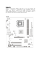
Rear Panel The rear panel provides the following connectors: Hardware Setup This chapter tells you how to install the CPU, memory modules, and expansion cards, as well as how to setup the jumpers on the mainboard. It also provides the instructions on connecting the peripheral devices, such as the mouse, keyboard, etc. While doing the installation, be careful in holding the components and follow the installation procedures. Central Processing Unit: CPU The mainboard supports Intel® Pentium 4 processor.
LGA775 CPU and Cooler Installation When you are installing the CPU, make sure the CPU has a cooler attached on the top to prevent overheating. If you do not have the cooler, contact your dealer to purchase and install them before turning on the computer. Meanwhile, do not forget to apply some silicon heat transfer compound on CPU before installing the cooler for better heat dispersion. Follow the steps below to install the CPU & cooler correctly.
1. Make sure your CPU cooler is firmly installed before turning on your system. 2. Check the information in PC Health Status of H/W Monitor in BIOS for the temperature. 3. Do not touch the CPU socket pins to avoid damage. 4. Whenever CPU is not installed, always protect your CPU socket pins with the plastic cap covered to avoid damage. 5. Please note that the mating/unmating durability of the CPU is 20 cycles. Therefore, we suggest you do not plug/unplug the CPU too often.
firmly into the connector. You may use the 20-pin ATX power supply as you like. If you’d like to use the 20-pin ATX power supply, please plug your power supply along with pin 1 & pin 13. There is also a foolproof design on pin 11, 12, 23 & 24 to avoid wrong installation. ATX 12V Power Connector: JPW1 This 12V power connector is used to provide power to the CPU. Floppy Disk Drive Connector: FDD1 The mainboard provides a standard floppy disk drive connector that supports 360K, 720K, 1.2M, 1.44M and 2.
BIOS Flash Jumper: JWP1 This jumper is used to lock or unlock area on BIOS. When unlocked, the BIOS boot block area can be updated. When locked, the BIOS boot block area cannot be updated. Fan Power Connectors: CPUFAN1/SYSFAN1/PWRFAN1 The 4-pin CPUFAN1 (processor fan) and 3-pin SYSFAN1 (system fan)/PWRFAN1 (power fan) support system cooling fan with +12V. When connecting the wire to the connectors, always take note that the red wire is the positive and should be connected to the +1connected to GND.
You can clear CMOS by shorting 2-3 pin while the system is off. Then return to 1-2 pin position. Avoid clearing the CMOS while the system is on, which will damage the mainboard. AGP (Accelerated Graphics Port) Slot The AGP slot allows you to insert the AGP graphics card. AGP is an interface specificadesigned for the throughput demands of 3D graphics. It introduces a 66Mthe graphics controller to directly access main memory. The slot supports AGP card for 8x/4x at 1.5v (3.3v is not supported).
SOLO TOP CASE 1 1 3 2 4 3 4 6 5 2 7 8 9 5 11 7 6 10 1 FDD 1 AC Out Connector 2 DVD,CD±R/RW 2 PS/2 K/B Port 3 Power Button 3 PS/2 Mouse Port 4 Reset Button 4 COM A Port 5 Speaker Out 5 VGA Port 6 MIC In 6 Parallel Port 7 USB Port 7 USB Port 8 LAN Port 9 MIC In 10 Line-Out 11 Line-In
BIOS Setup Power on the computer and the system will start POST (Power On Self Test) process. When the message below appears on the screen, press key to enter Setup. DEL: Setup F11: Boot Menu TAB: Logo If the message disappears before you respond and you still wish to enter setup, restart the system by turning it OFF and On or pressing the RESET button. You may also restart the system by simultaneously pressing , , and keys.
BIOS Setting Password Use this menu to set BIOS setting Password. Save & Exit Setup Save changes to CMOS and exit setup. Exit Without Saving Abandon all changes and exit setup. Current FSB Clock It shows the current FSB clock of . Read-only. Adjust CPU Ratio This item allows you to adjust the CPU ratio. Setting range is from [8] to [50]. Auto Detect DIMM/PCI Clock This item is used to auto detect the DIMM and PCI slots.
Adjust CPU/AGP/PCI Frequency This item allows you to select the CPU/AGP/PCI Front Side Bus clock frequency (in MHz) and overclock the processor by adjusting the FSB clock to a higher frequency. Memory Voltage Adjusting the DDR voltage can increase the DDR speed. Any changes made to this setting may cause a stability issue, so changing the DDR voltage for long-term purpose is NOT recommended.