Service Manual Auto Washer Model : DWF-750/752/800/802 753/755/803/805 756/758/806/808 ✔ Caution : In this Manual, some parts can be changed for improving, their performance without notice in the parts list. So, if you need the latest parts information,please refer to PPL(Parts Price List) in Service Information Center (http://svc.dwe.co.kr). DAEWOO ELECTRONICS CO., LTD.
ASHER AUTO WASHER AUTO WASHER AUTO WASHER AUTO WASHER AUTO WASHER AUTO WASHER AUTO WASHER AUTO WASHER AUTO WASH TO WASHER AUTO WASHER AUTO WASHER AUTO WASHER AUTO WASHER AUTO WASHER AUTO WASHER AUTO WASHER AUTO WASHER AU ASHER AUTO WASHER AUTO WASHER AUTO WASHER AUTO WASHER AUTO WASHER AUTO WASHER AUTO WASHER AUTO WASHER AUTO WASH TO WASHER AUTO WASHER AUTO WASHER AUTO WASHER AUTO WASHER AUTO WASHER AUTO WASHER AUTO WASHER AUTO WASHER AU ASHER AUTO WASHER AUTO WASHER AUTO WASHER AUTO WASHER AUTO WASHER AUTO
1. SPECIFICATIONS NO. DWF-750/753/756 ITEM DWF-752/755/758 1 POWER SOURCE POWER DWF-800/803/806 DWF-802/805/808 AVAILABLE IN ALL LOCAL AC VOLTAGE 50Hz 320W 2 CONSUMPTION 60Hz 300W(110~127V) / 340W(220V) MACHINE NET 28kg/28.5kg(pump) 28.5kg/29kg(pump) WEIGHT GROSS 31.5kg/32kg(pump) 32kg/32.
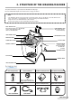
2. STRUCTURE OF THE WASHING MACHINE The parts and features of your washer are illustrated on this page. Become familiar with all parts and features before using your washer. NOTE • The drawing in this book may vary from your washer model. They are designed to show the different features of all models covered by this book, Your model may not include all features. • Page references are included next to same features. Refer to those pages for more information about the features.
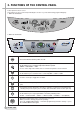
3. FUNCTIONS OF THE CONTROL PANEL Control panel has micom sensor. As the buttons are pressed, the lamps indicating the selection of your desired washing program will light up. 1. DWF-750/752/800/802 HOURS RES. CONTROL PROGRAM 2. DWF-753/755/803/805 • Press this switch to turn the power on or off. • It can be used to choose water temperature to be supplied. • As the button is pressed, water temperature will be repeated.
3. DWF-756/758/806/808 • Press this switch to turn the power on or off. • It can be used to choose water temperature to be supplied. • As the button is pressed, water temperature will be repeated. COLD → COLD+HOT → HOT • In case of the single valve model, there is no wash temperature selector function. • It can be used to adjust amount of water according to the size of the load to be washed.
4. DIRECTIONS FOR INSTALLATION AND USE § è Location Of Washer Check location where washer will be installed. Make sure you have everything necessary for correct installation. Proper installation is your responsibility. • Do not place or store your washer below 0˚C(32˚F) to avoid any damage from freezing. • Install the washer on the horizontal sold foor. If the washer is installed on an unsuitable floor, it could make considerable noise, vibrate and cause a malfunction.
§ è How to Connect the Inlet Hose Be careful not to mistake in supplying between the hot(maximum : 50˚C) and cold water. In using only one water tap or in case of attached one water inlet valve, connect the inlet hose to the cold water inlet valve. Do not over tighten : this could cause damage to couplings. FOR ORDINARY TAP 1 Pull down the collar of the inlet hose to separate it from the water tap adapter.
§ è How To Clean The Filter CLEANING THE LINT FILTER 1 2 Pull the Filter frame upward. 3 Turn the lint filter inside out, wash the lint off with water. Lint Filter Return the filter as it was, and insert the filter frame into the slot. Filter Frame CLEANING THE WATER INLET FILTER • Clean the filter when water leaks from the water inlet. 1 2 Pull the power plug out before cleaning it. 3 Turn off the water supply to the washer and separate the inlet hose. Pull the inlet filter out.
5. FEATURE AND TECHNICAL EXPLANATION Feature of the Washing Machine 1 The first air bubble washing system in the world. 2 Quiet washing through the innovational low-noise design. 3 The wash effectiveness is much more enhanced because of the air bubble washing system. 4 The laundry detergent dissolves well in water because of the air bubble washing system. 5 The adoption of the water currents to adjust the unbalanced load. 6 One-touch operation system.
Automatic Drainning time Adjustment This system adjusts the draining time automatically according to the draining condition. Good draining The washer begins spin process after drainage. Bad draining Draininig time is prolonged. No draining Program is stopped and gives the alarm.
Softener Dispenser This is the device to dispense the softener automatically by centrifugal force. This is installed inside the auto-balancer. FUNCTIONAL PRINCIPLE 1 Softener stays in room (A) when poured into softener inlet. 2 Softener moves from (A) to (B) by centrifugal force during intermittent spin process. 3 Softener flows from (B) to (C) during rinse process next to intermittent spin. 4 Softener moves from (C) to (D) by centrigfugal force during second intermittent spin.
Automatic Unbalance Adjustment This system is to prevent abnormal vibration during intermittent spin and spin process. FUNCTIONAL PRINCIPLE 1 When the lid is closed, the safety switch contact is “ON” position. 2 In case that wash loads get uneven during spin, the outer tub hits the safety switch due to the serious vibration, and the spin process is interrupted. 3 In case that P.C.B. ASS’Y gets “OFF” signal from the safety switch, spin process are stopped and rinse process is started automatically by P.C.B.
Lint Filter Much lint may be obtained according to the kind of clothes to be washed and some of the lint may also sticks to the clothes. To minimize this possibility a lint filter is provided on the upper part of the tub to filter the wash water as it is discharged from the water channel. It is good to use the lint filter during washing. Filter Filter Bleach Bleach Inlet Inlet Pulsator Pulsator HOW TO REPLACE LINT FILTER 1 Pull the filter frame upward.
Gear Mechanism Ass’y The proper water currents is made by the rotation of pulsator at a low speed to prevent the damage to the small sized clothes. Pulsator shaft Spin shaft One way clutch bearing Gear unit as Sun gear Internal gear Planetary gear Clutch spring Brake lever Clutch boss Gear pulley Motor Pulsator 1490 r.p.m (50Hz) Gear unit as 1 revolution Motor Pulsator Gear Unit as Gear Pulley 5 revolutions 138 r.p.m 720 r.p.m Tub Gear pulley Directly 720 r.p.
PRINCIPLE OF INTAKE & OUTLET OF THE AIR INTAKE : ARMATURE moves up, and BELLOWS inhales the air. At the same time, protector B is open and A is close. OUTLET : ARMATURE moves down, and BELLOWS exhausts the air. At the same time, protector B is close and A is opend. FUNCTIONAL PRINCIPLE OF TRANS & MAGNET ¡ The phase of A.C electric power changes to 60 cycle/second. ¡ The magnetic pole of trans core is changed by the change of the phase of A.C electric power. ¡ The core repeats push and pull (3600 times/min.
6. DIRECTIONS FOR DISASSEMBLY AND ADJUSTMENT Warning BEFORE ATTEMPTING TO SERVICE OR ADJUST ANY PART OF THE WASHING MACHINE, DISCONNECT THE POWER CORD FROM THE ELECTRIC OUTLET. Gear Mechanism Ass’y Replacement ¡ Raise the top plate on the outer cabinet. ¡ Remove outer tub cover from the tub ass’y. ¡ Loosen the pulsator mounting screw and remove ¡ Remove the spinner shaft flange nut by using ‘T’ ¡ Remove the tub ass’y. type box wrench.
¡ Lay the front of the washer on the floor. ¡ Remove four bolts mounting the plate-gear protect by ¡ Remove four bolts mounting the gear mechanism ass’y by using a box wrench. using a box wrench and remove plate-gear protect. ¡ Remove the V-belt. ¡ Pull out the gear mechanism assy.
Motor Synchronous And Valve Replacement(Non Pump Model) ¡ Lay the front of the floor. ¡ Loosen two special screw and motor synchronous. ¡ Take out the wire of motor synchonous from the bracket. ¡ Separate the motor sycnchronous from the base. ¡ Turn the valve by using screw driver as shown in picture. ¡ Remove the valve lid from the valve drain assy. Brake Adjustment ¡ Loosen the adjustment bolt and turn the adjustment bolt until the end of the bolt touches to the brake lever.
7.
How To Check The Clutch Spring Problem PROBLEM 1) THE LAUNDARY IS IN THE SPIN TUB UNEVENLY WHEN JUST STARTING SPIN PROCESS. 2) THEREFORE, IT CAUSE THE SERIOUS NOISE AND VIBRATION WHEN WASHING AND SPINNING PROCESS OR SUPPLING WATER IRREGULARY WHEN SPINNING PROCESS AND CAUSE SHORT OF SPIN PERFORMANCE. CHECKING METHOD IN THIS CASE, YOU MUST EMPTY THE SPIN TUB FIRST. 1) TO CHECK THE REVOLUTION OF SPIN TUB. IF THE SPIN TUB DOES NOT REVOLVE AND ONLY THE PULSATOR IS TURNING, THAT IS CLUTCH SPRING DEFECT.
The Process Of Disassemble Disassemble 1 No. Process Notice Use wrench or driver - ratchet handle - extension bar - socket : 10mm 1 Remove the protector Release screws marked 4-point 2 Remove the v-belt Use fixing jig for pulley as to see fig 1.
Disassemble 2 No.
The Process Of Assemble Assemble 1 No. Process Notice Check the uneven face of coupling is assembled upward 1 Assemble the coupling 2 Assemble the new clutch boss ass’y 3 Assemble the pulley - Push in the clutch boss ass’y with rotating on the clockwise direction.
Assemble 2 No. Process Assemble the fastening nut 5 6 Notice - Use fixing jig and 17mm socket wrench as if disassembling, as fastening torque about 100~200kgf-cm. - Check the end-play, up and downward and check the binding force, too much or not on bi-direct of rotation. Assemble the Belt 7 Assemble the protector keep distance 2~3mm Synchronous Motor 8 Final checking Clutch Tip 3.5~4.5 24 Drain Valve THE REPAIR Finally, check the distance between brake lever and control bolt.
8. TROUBLE SHOOTING GUIDE NOTES 1. When replace the P.C.B. ASS’Y do not scratch the surface of the P.C.B. ASS’Y. 2. Disconnect the power cord from the electric outlet. Concerning Water Supply PROBLEM CHECK POINT CAUSE Do you open the water tap? NO SOLUTION Open the water tap. YES YES Is the filter of the water inlet valve clogged with dirt? Clean the filter. NO WATER IS NOT SUPPLIED. Increase the water pressure. NO Is the water pressure sufficient? (0.
PROBLEM CHECK POINT Does the water supply continue while the power is turned off? CAUSE SOLUTION YES The water inlet valve is defective. Change the water inlet valve. YES The triac of P.C.B is defective. Change the P.C.B ASS’Y. NO Does the water supply start as soon as you press the power switch? NO WATER SUPPLY IS NOT STOPPED.
Concerning Draining PROBLEM CHECK POINT Do you install the drain hose properly? CAUSE NO SOLUTION Improper installation Install the drain hose properly. Malfunction of drainage by the foreign matter Remove the foreign matter from the pump housing Drain pump is defective Change the Drain pump P.C.B ASS’Y is defective. Change the P.C.B ASS’Y. YES THE WASHER DOES NOT DRAIN.
Concerning Spinning PROBLEM CHECK POINT CAUSE SOLUTION YES Close the lid. Is the lid open? NO Does the safety switch operate normally? NO Safety switch is defective. Change the safety switch. NO Improper connection of the connector. Connect the connector properly. P.C.B. ASS’Y is defective. Change P.C.B ASS’Y. Drain motor is defective. Change the drain motor. P.C.B ASS’Y is defective. Change the P.C.B ASS’Y. V-belt is defective. Change the V-belt. Motor is defective. Change the motor.
Concerning Operation PROBLEM CHECK POINT CAUSE SOLUTION NO Is the plug connect-ed to electric outlet? Connect the plug. YES YES THE INDICATOR LAMPS(L.E.D) DO NOT LIGHT UP WHEN THE POWER BUTTON IS PRESSED. Is Fuse opended? Change Fuse NO Is the condition of power button good? NO MOTOR ROTATES WHEN START/HOLD BUTTON IS NOT PRESSED. ABNORMAL NOISE DURING WASH PROCESS. Change P.C.B ASS’Y. Improper connection of the connector. Connect the connector properly. P.C.B. ASS’Y is defective. Change P.
9. PRESENTATION OF THE P.C.B ASS’Y Concerning Error Message MESSAGE CAUSE Improper installation of drain hose. Install drain hose properly. The drain hose is blocked up by foreign matter. Remove foreign matter from drain hose. Drain motor is inferior. Change drain motor. The water tap is closed. Open the water tap. The water inlet filter clogged. Clean the water inlet filter. It passes over the 30 minutes, yet it doesn’t come to assigned water level.
APPENDIX § è Wiring Diagram [non-pump] WIRING DIAGRAM 31
§ è [Non-Pump, Single Valve] 32 WIRING DIAGRAM
§ è [Pump] WIRING DIAGRAM 33
§ è [pump, single valve] 34 WIRING DIAGRAM
§ è Parts Diagram PARTS DIAGRAM 35
✔ Caution: In this Service Manual, some parts can be changed for improving, their performance without notice in the parts list. So, if you need the latest parts information, please refer to PPL(Parts Price List) in Service information Center(http://svc.dwe.co.kr) §§ è Parts List NO.
✔ Caution: In this Service Manual, some parts can be changed for improving, their performance without notice in the parts list. So, if you need the latest parts information, please refer to PPL(Parts Price List) in Service information Center(http://svc.dwe.co.kr) NO.
38 PARTS DIAGRAM
✔ Caution: In this Service Manual, some parts can be changed for improving, their performance without notice in the parts list. So, if you need the latest parts information, please refer to PPL(Parts Price List) in Service information Center(http://svc.dwe.co.kr) §§ è Parts List NO. PART NAME PART CODE SPECIFICATION REMARK B01 CABINET 3610809600 PAINTED STEEL SHEET 0.
40 PARTS DIAGRAM
✔ Caution: In this Service Manual, some parts can be changed for improving, their performance without notice in the parts list. So, if you need the latest parts information, please refer to PPL(Parts Price List) in Service information Center(http://svc.dwe.co.kr) §§ è Parts List NO. PART NAME PART CODE SPECIFICATION C01 BALANCER AS 3616104700 DWF-6010 C02 TUB I 3618808500 SUS 0.5T C03 TUB U 3618808601 PP C04 GUIDE FILTER 3612507000 DWF-6010NP C05 SPECIAL SCREW 3616003700 SUS 5.
42 PARTS DIAGRAM
✔ Caution: In this Service Manual, some parts can be changed for improving, their performance without notice in the parts list. So, if you need the latest parts information, please refer to PPL(Parts Price List) in Service information Center(http://svc.dwe.co.kr) §§ è Parts List NO.
§ è Circuit Diagram 1.
2.
DAEWOO ELECTRONICS CO., LTD. 686, AHYEON-DONG MAPO-GU SEOUL, KOREA C.P.O. BOX 8003 SEOUL, KOREA TELEX: DWELEC K28177-8 CABLE: “DAEWOOELEC” FAX: 82-2-360-7877 TEL: 82-2-360-7114 http://www.dwe.co.kr S/M NO. : WF750SE001 PRINTED DATE: JULY.