S/M NO : PASP42B001 42” PLASMA PDP TV PASP42B3D3S0 DPX-42D1NMSB DPX-42D1 1
CONTENS 1. Safety Precautions 2. Product Specification 2-1. DPX-42D1NMSB Product Specification 2-2. Available input signal 3. Block Diagram 3-1. Basic Block Diagram 3-2. Panel Block Diagram 4. A/V Block Diagram 5. Description of POWER PCB 5-1. Input/Output pin assignment & specification 5-2. Output specification 6. Service Mode 6-1. ENTERING METHODE OF SERVICE MODE 6-2. DEFAULT VALUE OF SERVICE MODE 7. Adjusting Method 7-1. Adjusting WHITE BALANCE 7-2 . POWER BOARD Adjustment 8. SOFTWARE UPGRADE Method 8-1.
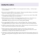
1.Safety Precautions (1) When moving or laying down a PDP Set, at least two people must be working. towards the PDP Set. Avoid any impact (2) Do not leave the broken PDP Set on for a long time. To prevent any further damages, after check the broken Sets condition, make sure to turn the power (AC) off. (3) When opening the BACK COVER, turn off the power (AC) to prevent electric shock. When a PDP is on, high voltage and high current exist inside the Set.
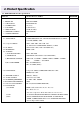
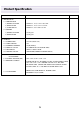
2. Product Specification 2-1. DPD-42D1GMB Product Specification ITEM SPECIFICATION 1. GENERAL 1-1MODEL NO 1-2. CHASSIS NO 1-3. SCREEN SIZE 1-4. COUNTRY 1-5. RESOLUTION 1-6. REMOTE CONTROL 1-7. TUNING METHOD DPX-42D1NMSB PASP42B3D3S0 42”(16:9) South America 852(H) X 480(V) DDR-2020C03 FS 2. ELECTRICAL 2-1. VIDEO INPUT 2-2. Component INPUT 2-3. PC INPUT 2-4. HDMI INPUT 2-5. TV INPUT 1) COLOR STANDARD 2) ANTENNA IN 3) RECEPTION CHANNEL 4) IF & SUBCARRIER 2-6. SOUND INPUT 2-7. SPEAKER OUTPUT 2-8.
Product Specification ITEM 3. MECHANICAL 3-1. APPEARANCE 1) WITHOUT STAND 2) WITH STAND 3) CARTON BOX 3-2. WEIGHT 1) WITHOUT STAND 2) WITH STAND 4. OPTICAL 4-1. SCREEN SIZE 4-2. ASPECT RATIO 4-3. NUMBER OF PIXELS 4-4. DISPLAY COLOR 4-5. CELL PITCH 4-6. VIEWING ANGLE 5. USERCONTROL & ACCESSORIES 5-1 CONTROL BUTTON(SET) 5-2. REMOTE CONTROL 5-3. ACCESSORIES SPECIFICATION WxHxD= 1,113.5 x 744 x 101.5 mm WxHxD= 1,113.5 x 822 x 351 mm WxHxD= 1,278 x 860 x 377 mm 29.5 Kg Net 38.5 Kg Net 42 inches(106.
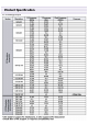
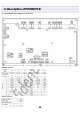
Product Specification 2-2.
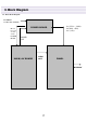
3. Block Diagram 3-1. Basic Block Diagram AC INPUT AC100~240V 50/60 Hz M+7V D+3.
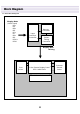
Block Diagram 3-2.
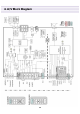
4.
5. Description of POWER PCB 5-1.
5. Description of POWER PCB 5-2.
6. Service Mode 6-1. ENTERING METHODE OF SERVICE MODE 1 => MUTE => (RECALL ) => MUTE BUTTON on the remote control (You can exit from Service mode by press power button on the remote control) 6-2. DEFAULT VALUE OF SERVICE MODE (1) DEFAULT VALUE OF Color Control DPX-42D1NMSB(Default Value) Sub Brightness 123 Sub Contrast 100 Red Offset 122 Red Gain 122 Green Offset 117 Green Gain 100 Blue Offset 127 Blue Gain 119 (2) Calibration Mode Do not adjust. (3) Option Table Mode Do not adjust.
7. Adjusting Method 7-1. Adjusting WHITE BALANCE (1) Input 5 STEP GRAY SCALE PATTERN to Video Input Terminal. (2) Set the SCREEN MODE to NORMAL. (3) Enter SERVICE MODE by inputting remote controllers [“1” => “MUTE” => “RECALL”=> “MUTE” BUTTON], and then select “COLOR CONTROL” and check Default Values of SERVICE MODE Items. (4) Attach WHITE BALANCE METER(FACTORY USE METER: CA-100) SENSOR to 80% Gray Scale part. (5) Adjust WHITE BALANCE by varying R,G,B GAIN -.
Adjusting Method 7-2 POWER BOARD Adjustment (1) Turn On the PDP TV and Display Full white Pattern (2) Check the Voltage Label (3) Check the Voltage by using Multimeter each Test Point (4) Adjust the each Voltage Very slowly, witted voltage at the label Voltage Label Test Point Adjust Volume 14
8. SOFTWARE UPGRADE Method 8-1. Preparation (1) IBM PC with Serial Port (D-Sub 9 Type) (with Windows98, Windows ME, Windows NT, Windows 2000, Windows XP) (2) Update Cable (D-sub 9 pin mail to Phone Jack) 8-2. UPGRADE Method (1) Check the com port is available. if com port is not available, you must install com port. (2) Plug out power cable form PDP TV’s Power inlet. (3) Connect phone jack to PDP TV’s upgrade port. (4) Connect D-sub 9pin jack to computer com port. (5) Run PC’s Flashexpress_nologo.
SOFTWARE UPGRADE Method (6) Select Upgrade folder by pressing button and Select firmware folder (7) Select COM port and baud rate(1152000) (8) Select WARE3.INF.
SOFTWARE UPGRADE Method (9) Press the button and plug in power code to PDP’s power inlet. (10) When all files Upgrade are complete, “Download successful” (below) will come out. (11) Check Firmware Version and reset PDP TV. * Reset method 1. Turn on the TV 2. Enter Service mode(1 -> Mute -> Recall -> Mute.) 3. Check Firmware Version. (Select “6. Version”) 4. Reset. (Select “7.
9. SET Disassemble/Assemble Method 9. SET Disassemble/Assemble Method .9-1. Facts You Must Know When Disassembling/Assembling PDP SET (1) The sheet must be clean, smooth and thick enough to reduce any impact which might occur while handling. (2) BACK COVER can’ t be opened without separating the STAND from the PDP SET. (3) BACK Shield Case can’ t be opened without separating the KEY PCB (4) When disassemble PDP set. Do not disassemble Frame Main L/R screw, that may be cause of drop PDP Panel.
10. Main PCB Trouble Diagnosis 10-1. VIDEO & JACK PCB Trouble Diagnosis Check Start NO Does “No signal” screen appear? Is there a weak discharge on the screen? YES 1. Confirm AC connection 2. Confirm Cable connection of Power PCB 3. Reassemble or change Power PCB NO YES NO Is the signal input Jack correctly connected? Check the connection of Jack (PDP or AV device) Is the LVDS Cable correctly connected? YES 1. Confirm Cable connection of Video PCB 2.
Main PCB Trouble Diagnosis 10-3. Key & IR Trouble Diagnosis Check Start NO LED light is appear? 1. Check the connection of Key_LED_IR cable 2. Change the Key_LED_IR cable 3. Change IR_LED PCB 4. Change Video PCB YES Dose PDP TV turn on by use remocone? NO 1. Change IR_LED PCB 2. Change Video PCB YES Check the KEY Lock function OFF 1. Change KEY PCB 2. Change Video PCB ON Check A/V Device function 10-4. Remocon Trouble Diagnosis Check Start LED light is appear? NO 1.
11. TROUBLE SHOOTING 11-1. Facts you must know when Trouble diagnosis or repairing (1) Sets trouble diagnosis and repairing means Module Exchange. In other words, find out which PCB modules are not working and replace them with normal PCB modules. Do not need to fix broken PCB modules in themselves. (2) This TROUBLE SHOOTING list only contains representative and simple PCB trouble diagnosis and Module Exchange method.
12. ASSEMBLY LIST No Part No. Part Name Discription 1 PASP42B3S3SD Main+A/D board PIONEER 42" B3 Panel, 218 AD board (SOUTH AMERICA) 1 2 PASP42B3S3SV Main+A/V board PIONEER 42" B3 Panel, 218 AV board (SOUTH AMERICA) 1 3 PAS-SIG6LIXA LED_IR BOARD T=1.6*100*20/2L, IR&LED 1 4 PAS-SIG6KEYA KEY BOARD T=1.6*74*33.
ASSEMBLY LIST No Part No. Part Name Discription 41 DP4260S653A Gasket Shield 1.5T*20W*600L 1 42 DP4200S654A Insulation Sheet-S Non-woven fabric/0.8T/15W*45L 4 43 DP4210S655A Insulation Sheet-L Non-woven fabric/0.8T/25W*440L 1 44 DP4260S640A Pad Top/R EPS/30T 1 45 DP4260S650A Pad Top/L EPS/30T 1 46 DP4260S660A Pad Bottom/R EPS/30T 1 47 DP4260S670A Pad Bottom/L EPS/30T 1 48 DP4260S647A Pad Top PE/Form 1 49 DP5000S672A Poly Bag LDPE 0.
ASSEMBLY LIST No Part No.
13.
14.
Assemble Diagram 27
Assemble Diagram 28
Assemble Diagram 29
Assemble Diagram 30
Assemble Diagram 31
Assemble Diagram 32
Assemble Diagram 33
Assemble Diagram 34
Assemble Diagram 35
Assemble Diagram 36
Assemble Diagram 37
Assemble Diagram 38
Assemble Diagram 39
Assemble Diagram 40
Assemble Diagram 41
Assemble Diagram 42
Assemble Diagram 43
Assemble Diagram 44
Assemble Diagram 45
Assemble Diagram 46
Assemble Diagram 48
Assemble Diagram 49
Assemble Diagram 50
Assemble Diagram 51
Assemble Diagram 52
Assemble Diagram 53