FT32600001
SPECIFICATIONS * is option code 1. Model Information Refrigerant Type R-134a R-600a Model No.
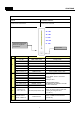
SPECIFICATIONS 2. Interior Parts ※ The real features are model dependent 1 10 2 3 4 5 11 6 7 8 9 1. Freshfood compartment LED 7. Temperautre control Knob 2. Multi-Duct 8. Freezer Case (3EA) 3. Freshfood compartment Shelves 9. Adjustable Foot 4. Fresh Care Crisper (option ) 10. Dairy Pocket 5. Wine Keeper (option) 11. Freshfood compartment Pocket 6.
SPECIFICATIONS 3.
SPECIFICATIONS 4.
FUNCTIONS 1. DISPLAY INPUT CONTROL OBJECT PCB Control Panel Buttons PCB Control Panel LED 5th LED 4th LED 3rd LED 2nd LED 1st LED Temperature adjustment button for refrigerator compartment. “Super Cool” No 1 2 3 4 LED DISPLAY FUNCTION OPERATION 3rd LED TEMP STEP “NOR” Initially position 4th LED TEMP STEP “MAX-NOR” Push “TEMP” button 1 times. 5th LED TEMP STEP “MAX” Push “TEMP” button 2 times. 1st LED TEMP STEP “MIN” Push “TEMP” button 3 times.
FUNCTIONS 2. Temperature Control of Refrigerator Compartment INPUT CONTROL OBJECT PCB Control Panel “TEMP” Buttons PCB Control Panel LED COMPRESSOR, FAN R-sensor A. “TEMP” Button 1. Temperature control of Refrigerator compartment 2. 5 step mode of successive temperature mode 3. Initial mode by power input: step “NOR” 4. Temperature will be set if the button doesn’t get pressed again within 5 sec.
FUNCTIONS 3. Defrost Mode INPUT CONTROL OBJECT Total COMP Work Time / COMP Working Rate Total Door Open Time / RT Defrost Mode Conditions of Defrost Mode A. When total operation time of compressor becomes: 6, 8, 10, 12 hours. - any error mode-R1, D1, F3, C1, RT/S, Door SW error- happens. - or, running rate of COMP (per 2hrs of total operation time) is more than 80%. - or, total door open time is over 3 minutes. - or, ambient temperature (RT) is more than 40C. B.
FUNCTIONS 3. Defrost Mode INPUT CONTROL OBJECT Total COMP Work Time / COMP Working Rate Total Door Open Time / RT Defrost Mode Initial Defrost A. When initial power input or returning power failure. if the temperature at the Defrost Sensor is below 3.5 C, Defrost Mode starts. ( It prceeds from 'PRE-COOL' ), [ PRE-COOL - Heater On - Pause (10min) - Normal Operation ] B. Initial defrost mode starts after 'Prevention of Compressor Restart'. ( Refer to function No.
FUNCTIONS 4. Prevention of Compressor Restart INPUT CONTROL OBJECT COMP COMP. doesn’t work after COMP turns off even though R-sensor is on condition. (This is to protect comp.) A. General operation (Temp. at the RT sensor is over 20C): The COMP can’t be on within 6 min. B. Operation of LOW RT (Temp. at the RT sensor is below 19C): The COMP can’t be on within 30 min. (But the COMP can be on after 6min when the doors open more than 20 seconds.) 5.
FUNCTIONS 6. Control of R-sensor OFF Point INPUT CONTROL OBJECT ”J1” , “J2” On Main PCB Control Resistance of R sensor OFF Point A. LOW COOLING OPTION ( Weak Cooling ) - When the refrigeration of refrigerator is poor or weak though Fan and COMP are working continuously, the following actions are recommended for service. - Resistance (R47) : Default resistance (31.4Kohms) - Resistance (R45) : Cut the “J1” off to reduce basic resistance by 1.5°C.
FUNCTIONS 7. Error Display INPUT CONTROL OBJECT PCB Control Panel Buttons / Door LED Lamp - ERROR DISPLAY - To check the appliance has error or not, push TEMP button 5 times while opening the refrigerator. door. - To stop the Error Display Set, push “TEMP” button 1 times, or wait 4 minutes. A. R1 ERROR (It happens when R-Sensor is OPEN or SHORT) - DISPLAY : 3rd LED is on & off continually. - CONTROL : ; Controlled by the following condition of RT ; When “RT ERROR” happens at the same time, “COMP.
FUNCTIONS 8. Function Key Summary Table MODE Forced(Quick) Defrost Mode Pull Down Mode Error Display Action Button / Remark How to enter the Mode S-COOL 5 times + Refrigerator door open How to terminate After mode end or unplug. Display 3rd and S-COOL LED is on. How to enter the Mode TEMP button 30 times How to terminate After mode end or unplug. Display 1st and S-COOL LED is on. How to enter the Mode TEMP 5 times + Refrigerator door open How to terminate After 4 minutes or unplug.
DISASSEMBLY 1. Front PCB ( some parts can vary from the actual appearance. ) Procedure No 1 Procedure No 3 Remove cap cover. 2 Pull the FCP FIXTURE UP by using (-)driver. 4 Separate the F-PCB housing from refrigerator. After separating F-PCB from fixture , Be careful not to scratch the cabniet surface.
DISASSEMBLY 2. Door Switch No Procedure No 1 Procedure 3 Remove top cover hinge screw with (+) driver. Remove the Door Switch from the cover hinge. 2 4 Separate the Cover hinge by using driver. Disconnect door switch connector. Be careful not to scratch the cabniet surface. 3. Multi-Duct As ( In Freshfood Compartment ) No Procedure No Procedure 1 Remove screw cap with (-) driver(2 points) 3 2 Unscre 2 points with Unscrew ith ((+)driver )dri er Disconnect the Sensor wire ire housing.
DISASSEMBLY 4. Freezer Louver As No Procedure Procedure No 1 4 Unscrew the fixing screw to remove the Louver F As Remove 3 screws in order to disassemble Louver F As. 2 5 Remove the Louver F As pulling the top side. When disassembling check the Knob position. 3 6 L M H Disconnect Fan motor wire housing.
DISASSEMBLY 5. LED Lamp ( In Freshfood Compartment ) No Procedure 1 Using a thin driver, Pull both locker and Separate a Window LED from Liner. 2 Unscrew 2 points with (+) driver 3 Disconnect LED PCB form housing.
How to change Door opening Dirction (Reversible) No Procedure Procedure No Button 1 Hidden Wire 6 Cover Bushing After hiding door wire harness, remove the button Door Remove top cover hinge screw with (+) driver. 2 Switch and Cover Bushing. 7 After unscrewing the Cover Hinge Harness *T *L, Separate the Cover hinge by using driver. disclose the door wire harness. Stopper 3 8 Reassemble the cover and button door switch. And also assemble the door stopper to opposite side.
How to change Door opening Direction (Reversible) No Procedure No 11 Procedure 14 Screw the middle hinge to fix the Freezer Door. Connect the wire harness to door swtich. ( Washer should be up. ) ( Be careful the dircetion. ) 12 15 Also assemble wire cover on the top plate. ( On the right 13 Change the plate position and separate door switch. 18 Assemble Door and hing cover.
How To Change Door Position 1-1. Remove the Door As a. Remove 'Top Cover Hinge' and 'Top Hinge' b. Separate 'Refrierator Door'. c. Remove 'Middle Hinge' d. Separate 'Freezer Door'. ⓑ e. Remove 'Cover Bracket'. ⓓ f. Remove 'Under Hinge'. 1-2. Reverse the Door Accessories ⓙ ⓖ g. Reverse the position of 'Cover Bushing Refrigeraor Door' - Unscrew and remove 'Harness Cover'. - Take out 'Left Door Harness' and assemble 'Harness Cover' on 'Right Door Harness'. h.
How To Change Door Position 1-3. Reassemble the Freezer and Refrigerator Door j. Assemble the 'Under Hinge' on the left. k. Attach the 'Freezer Door' to Cabniet. l. Assemble the 'Middle Hinge' on the left. ⓜ m. Attach the 'Refrigerator Door' to Cabinet. ( Be careful not to fall down ) n. Assemble 'Top' hinge and connect the FCP wire. o. Connect the 'Door Switch' wire housing. Assemble the 'Door Switch' on the other side. ⓟ p. Assemble the 'Cover Bracket'.
How To Charge R-600a Refrigerant 1. Safety Warning ( R-600a Refrigerant Models) This appliance contains a certain amount of isobutane refrigerant (R600a) a natural gas with high environmental compatibility that is, however, also combustible. When transporting and installing the appliance, care should be taken to ensure that no parts of the refrigerating circuit are damaged. Refrigerant squirting out of the pipes could ignite or cause an eye injury.
How To Charge R-600a Refrigerant 3. Process Summary 1st Step. R-600a ref. discharging 2nd Step. Removing the remaning refrigerant - Connect the discharging hose to the outdoors. - Time : 7 min. 4th Step. Welding coupling pipe Coupling cap and gas charging cap should be seperated before welding. 3th Step. Exchanging comp. & dryer / pipe welding - For removing of remaning refrigerant., connect the discharging hose to the vacuum pump -Time : 10min - Exchange Comp.
How To Charge R-600a Refrigerant NO. SVC process Image Details 1. And then, connect the vacuum pump to the outlet of discharging hose 4 Remov ing the remaining ref. ※Vacum pump should be placed at the outdoor where is able to clear air easily. ※ It should have enough time more than 10 minutes to discharge. 1.
How To Charge R-600a Refrigerant NO. SVC process Image Details 1. Weld after inserting the coupling pipe to the compressor. 9 Coupling pipe welding ※ Use the wet cloth for preventing the other part of machinery-room from damage. 1. Reassemble the valve ass'y with coupling pipe to clockwise. 2. Connect the blue hose of the guage to the coupling pipe and the yellow hose 10 Valv e reass' y & guage connecting to the vacuum pump. 3. Open the blue guage lever and start the vacuum pump 1.
How To Charge R-600a Refrigerant NO. SVC process Image Details 1. Conect can adapter to the coupling pipe. 14 2. Charge the ref. with open lever slowly. Connecting of coupling pipe & adapta ※ Refrigerant should never leak in the room. 1. On the power of refrigerator and then start to charge the ref. (10min) 15 Charging ※ Charge the ref. until going out the water vapour condensing on the can outlet. 1. Check the leakage. 16 Leakage Test ※ You must rework from Step.1 when the leakage is detected.
Cabinet Cabinet Compartment Q'ty NO PART-CODE 1 - 2 PART NAME SPEC. T405.. T425.. T455..
Cabinet Compressor Compartment Q'ty NO PART-CODE 12 3010349300 13 OPTION PART NAME T405.. T425.. T455.. BASE COMP AS RFP-340 1 1 1 CORD POWER AS RFP-340 1 1 1 1 1 1 4 4 4 4 4 4 1 1 1 1 1 1 LZ88CY (A+,EUROPE) 3956188C50 14 3956158K50 COMPRESSOR 16 3016002500 SPECIAL WASHER SK-5 T0.
Cabinet Refrigerator & Freezer Compartment Q'ty NO 27 PART-CODE 3017065200 PART NAME EVA AS 3017068200 27-1 30127694100 HARNESS D SENS 3012769400 27-2 29 SPEC. R-134a R-600a R-134a R-600a 3012822000 HEATER D AS R-134a (GLASS) 3012823000 HEATER SHEATH AS R-600a 3018927900 LOUVER F AS RFP-341, AC FAN T405.. T425.. T455..
Cabinet Refrigerator & Freezer DOOR Compartment NO PART-CODE PART NAME T405.. T425.. T455.. 1 x x x 1 x x x 1 1 x x x 1 x x x 1 RFP-326 1 x x RFP-346 x 1 x RFP-356 x x 1 1 1 1 1 1 1 30100A6210 BLACK 30100A6310 39 30100A6410 ASSY R DR 30100A6200 WHITE 30100A6300 30100A6400 3012327700 391 3012321200 GASKET R DR AS 3012327800 40 3012037300 FIXTURE F PCB AS 3012037310 40-1 3012035800 FIXTURE F PCB 3012035810 Q'ty SPEC.