S/M No. : 3113907100 Service Manual Split System Air Conditioner Model: DSB-070LH/DSB-071LH DSB-091LH/DSB-092LH DSB-121LH/DSB-122LH DSB-123LH DSB-182LH/LH-R DSB-183LH-R DSA-183LH-R DSB-240LH-R DSA-240LH-R ✔ Caution : In this Manual, some parts can be changed for improving, their performance without notice in the parts list. So, if you need the latest parts information,please refer to PPL(Parts Price List) in Service Information Center (http://svc.dwe.co.kr). by Nemko DAEWOO ELECTRONICS CO., LTD.
Contents CONTENTS 1. Specifications..........................................................................................................2 2. Outline and Dimensions.......................................................................................11 3. Operation ..............................................................................................................20 4. Wiring Diagram.....................................................................................................44 5.
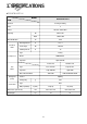
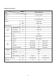
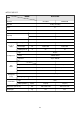
1. SPECIFICATIONS ◆DSB-070LH/071LH MODEL DSB-070LH /071LH ITEM Function Cooling & Heating Class T Power AC 220~ 240V/ 50Hz Capacity W 2,051/2,051 Btu/h 7,000/7,000 l/h 0.89 Running Current A 3.1/3.1 Power Input W 740/720 Starting Current A 18 Dehumidification Electrical Data Compressor Fan Motor Type Rotary Model RBB075A011 Capacitor 25µF/370VAC Indoor Unit Outdoor Unit Type Cross flow fan Propeller fan Capacitor 1.0µF 400VAC 1.
◆ DSB-091LH/092LH MODEL DSB-091LH /092LH ITEM Function Cooling & Heating Class T Power AC 220~240V/ 50Hz Capacity W 2,637/2,637 Btu/h 9,000/9,000 l/h 1.15 Running Current A 4.5/4.5 Power Input W 1,000/1,000 Starting Current A 24 Dehumidification Electrical Data Compressor Type Rotary Model RBB100A011 Capacitor Fan Motor 30µF / 370VAC Indoor Unit Outdoor Unit Type Cross flow fan Propeller fan Capacitor 1.0µF 400VAC 1.
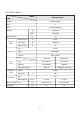
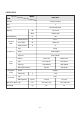
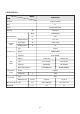
◆ DSB-121LH/122LH MODEL DSB-121LH/122LH ITEM Function Cooling & Heating Class T Power AC 220~240V/ 50Hz Capacity W 3,663/3,956 Btu/h 12,500/13,500 l/h 1.6 Running Current A 7.0/6.5 Power Input W 1,500/1,410 Starting Current A 37 Dehumidification Electrical Data Compressor Type Rotary Model RCB 150A001 Capacitor 35µF/ 370VAC Division Fan Motor Indoor Unit Outdoor Unit Type Cross flow fan Propeller fan Capacitor 1.0µF 400VAC 3.
◆ DSB-123LH MODEL DSB-123LH ITEM Function Cooling & Heating Class T Power AC 220~240V/ 50Hz Capacity W 3,517/3,810 Btu/h 12,000/13,000 l/h 1.28 Running Current A 6.8/7.3 Power Input W 1,500/1,550 Starting Current A 37 Dehumidification Electrical Data Compressor Type Rotary Model RCB 150A001 Capacitor 35µF/ 370VAC Division Fan Motor Indoor Unit Outdoor Unit Type Cross flow fan Propeller fan Capacitor 1.5µF 400VAC 3.
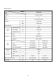
◆ DSB-182LH MODEL DSB-182LH ITEM Function Cooling & Heating Class T1 Power AC 220~240V/ 50Hz Capacity W 5,129/5,422 Btu/h 17,500/18,500 l/h 2.3 Running Current A 9.65/10 Power Input W 2,150/2,235 Starting Current A 49 Dehumidification Electrical Data Compressor Fan Motor Type Rotary Model SHW33TC4-U Capacitor 50µF / 370VAC Indoor Unit Outdoor Unit Type Cross flow fan Propeller fan Capacitor 1.
◆ DSB-182LH-R/DSB-183LH-R MODEL DSB-182LH-R ITEM DSB-183LH-R Function Cooling & Heating Class T1 Power AC 220~240V/ 50Hz Capacity Dehumidification Electrical Data W 5,275/5,275 5,275/5,560 Btu/h 18,000/18,000 18,000/19,000 l/h 2.3 Running Current A 9.2/9.5 9.5/9.
◆ DSA-183LH-R MODEL DSA-183LH-R ITEM Remark JIS C9812 Function SAA385386 Cooling & Heating Class T1 Power AC 220V / 60Hz W 5275.5/5422 4500/5400 Btu/h 18,000/18,500 15354/18425 Capacity Dehumidification Electrical Data Compressor Fan Motor l/h 2.3 Running Current A 9.4/8.8 10.4/8.
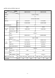
◆DSB-240LH-R MODEL DSB-240LH-R ITEM Function Cooling & Heating Class T1 Power AC 220~240V/ 50Hz Capacity W 7,034/7,034 Btu/h 24,000/24,000 l/h 2.67 Running Current A 13.4 / 13.
◆DSA-240LH-R MODEL DSA-240LH-R ITEM Remark JIS C9812 Function SAA385386 Cooling & Heating Class T1 Power AC 220V / 60Hz W 7,034/7,034 5,129 Btu/h 24,000/24,000 17.5 Capacity Dehumidification Electrical Data Compressor Fan Motor l/h Running Current A 11.5/11.
2.
DSB-071LH/DSB-092LH 750 Connecting Pipe Plate Mounting REMOTE CONTROLLER REMOCON Grille Insert 245 Frame Grille Body 179 Plate Mounting 12
DSB-121LH/122LH Filter - L Connecting Pipe Plate Mounting Plate Mounting Body Frame Grille Grille Insert 194 REMOTE CONTROLLER REMOCON 13 406 925 Filter - R 285
◆DSB-123LH 14
DSB-182LH/LH-R Filter-L Connecting Pipe 453 1035 Filter-R Plate Mounting REMOCON Grille Insert 1035 Body 322 15
DSB-183LH-R/DSA-183LH-R/DSB-240LH-R/DSA-240LH-R Connecting Pipe Filter-L 430 710 1080 Grille Insert REMOCON Body 200 Frame Grille Plate Mounting Filter-R 298 16
2 OUTDOOR UNIT ◆DSB-070LH/071LH/091LH/092LH/121LH/122LH/123LH 17
DSB-182LH/LH-R/DSA-183LH-R/DSB-183LH-R Inlet Outlet Foot Cushion Inlet Outlet Cabinet Front 800 320 Foot Handle Service Valve 615 Cabinet Side Panel Top Guide Support 18
DSB-240LH-R/DSA-240LH-R Inlet 873 Cabinet front foot 323 380 Service Cover Cabinet Side Service valve 699 19
3. OPERATION 1 NAME AND FUNCTION OF PARTS Indoor Unit ◆DSB-070LH/DSB-091LH Electrostatic Filter(Option) Removes dust and particles from the air Deodorizing Filter(Option) Removes bad smells from the air. Air Inlet Lamp Antibacterial Filter Removes dust and prohibits germs.
◆ DSB-071LH/DSB-092LH Electrostatic Filter(Option) Removes dust and particles from the air Air Inlet Deodorizing Filter(Option) Removes bad smells from the air. Lamp Antibacterial Filter Removes dust and prohibits germs.
◆ DSB-121LH/122LH Electrostatic Filter Air Inlet Removes dust and particles from the air ;;;;;;;;;;;;;;;;;;;;;;;;;;;;;;;;;;;;;;;;;;;;;;;;;;;;;;;;;;;;;;;;;; ;;;;;;;;;;;;;;;;;;;;;;;;;;;;;;;;;;;;;;;;;;;;;;;;;;;;;;;;;;;;;;;;;; ;;;;;;;;;;;;;;;;;;;;;;;;;;;;;;;;;;;;;;;;;;;;;;;;;;;;;;;;;;;;;;;;;; ;;;;;;;;;;;;;;;;;;;;;;;;;;;;;;;;;;;;;;;;;;;;;;;;;;;;;;;;;;;;;;;;;; ;;;;;;;;;;;;;;;;;;;;;;;;;;;;;;;;;;;;;;;;;;;;;;;;;;;;;;;;;;;;;;;;;; ;;;;;;;;;;;;;;;;;;;;;;;;;;;;;;;;;;;;;;;;;;;;;;;;;;;;;;;;;;;;;;;;;; Antibacterial Fi
◆ DSB-123LH Deodorizing Filter Air Inlet Electrostatic Filter Removes bad smells from the air. Removes dust and particles from the air Lamp Antibacterial Filter Air Outlet Removes dust and prohibits germs.
◆ DSB-182LH/DSB-182LH-R Deodorizing Filter Removes bad smells from the air. Test/Emergency/ Remote Switch Electrostatic Filter Removes dust particles from the air. Air In Slide to select the desired position. Indoor Cover Air Cleaning Filters Remote Sensor Removes dust and prohibits germs. Indicators Cold Air Indicate the AC setting. Fan Direction (Up/Down) Fan Direction (Left/Right) . MP TE /OFF ON DE MO P EE SL R.
◆ DSB-183LH-R/DSA-183LH-R/DSB-240LH-R/DSA-240LH-R Deodorizing Filter Removes bad smells from the air. Electrostatic Filter Removes dust particles from the air. AIR IN Indoor Cover Air Cleaning Filters Removes dust and prohibits germs. AIR OUT Fan Direction (Left/Right) Remote Sensor Fan Direction (Up/Down) Emergency/Remote Switch Indicators Indicate the AC setting. R.
◆ DSB-070LH/DSB-091LH Indoor Unit Display Switch Panel ■Remote Control Signal Receiver This place is the part to receive the signal if it receives the signal, you can hear the signal “beep. “beep. beep.” EMR. REMOCON ■ There is a switch panel at inside of Front Panel. At the time of operating, open the Front Panel. ON (Red) Lights when the operation is going on. Air clean (Green) Timer (Yellow) Lights during the time reservation mode.
◆ DSB-071LH/DSB-092LH Indoor Unit Display Switch Panel ■Remote Control Signal Receiver This place is the part to receive the signal if it receives the signal, you can hear the signal “beep. “beep. beep.” EMR. REMOCON ■ There is a switch panel at inside of Front Panel. At the time of operating, open the Front Panel. ON (Red) Lights when the operation is going on. Air clean (Green) Timer (Yellow) Lights during the time reservation mode.
◆ DSB-121LH/122LH Indoor Unit Display Switch Panel Remote Control Signal Receiver This place is the part to receive the signal if it receives the signal, you can hear the signal "beep, beep". EMERGENCY REMOTE * There is a switch panel at inside of Front Panel. At the time of operating, open the Front Panel. ON AIR CLEAN QUICK TIMER Emergency switch can be used when the remote controller is lost or testing. ON (Red) Timer (Yellow) Lights when the operation is going on.
◆ DSB-123LH Indoor Unit Display Switch Panel ■ Remote Control Signal Receiver This place is the part to receive the signal if it receives the signal, you can hear the signal “beep. beep”. REMOCON EMERGENCY REMOCON EMERGENCY Air clean (Green) ON (Red) Lights when the operation is going on. Timer (Yellow) ■There is a switch panel at inside of Front Panel. At the time of operating, open the Front Panel. Lights during the time reservation mode. Quick (Red) Lights during the time Quick Mode.
◆ DSB-182LH/182LH-R Indoor Unit Display Switch Panel ■ Remote Control Signal Receiver This place is the part to receive the signal if it receives the signal, you can hear the signal “beep. beep”. EMERGENCY REMOTE Timer Quick Airclean ON ■ There is a switch panel at inside of Front Panel. At the time of operating, open the Front Panel. Timer (Yellow) Lights during the time reservation mode. ON (Red) Lights when the operation is going on.
◆ DSB-183LH-R/DSB-240LH-R/DSA-240LH-R Indoor Unit Display Switch Panel ■ Remote Control Signal Receiver This place is the part to receive the signal if it receives the signal, you can hear the signal “beep. “beep, beep.” REMOCON EMERGENCY EMERGENCY REMOCON ON (Red) Lights-on during the operation Timer (Yellow) Lights-on during the time of reservation mode. Air clean (Green) Lights-on during the operation Quick (Red) Lights-on during the time of Quick Mode.
Outdoor Unit ◆ DSB-070LH/071LH/DSB-091LH/092LH/DSB-121LH/122LH/123LH Connection Cover Remove cover to access the AC connection to the indoor unit. AIR IN Connection Wire Connecting Pipe AIR OUT Drain Hose Service Valves The indoor and outdoor units are connected by copper tubes which are connected here.
◆ DSB-182LH/LH-R / DSA-183LH-R/DSB-183LH-R AC Cover Remove cover to access the AC connection from this unit to the indoor unit. AIR IN Connection Wire Drain Hose COPPER TUBING AIR OUT Service Valves The indoor and outdoor units are connected by copper tubes which are connected here. Grounding Screw Ground the unit here.
◆ DSB-240LH-R / DSA-240LH-R Connection wire Air Inlet Drain Hose Air Outlet Connection Pipe 34
2 REMOTE CONTROLLER Name of Each Button ◆ DSB-070LH/DSB-071LH/DSB-091LH/DSB-092LH/DSB-121LH/DSB-122LH/ DSB-123LH/DSB-183LH-R/DSA-183LH-R/DSB-240LH-R/DSA-240LH-R Display Displays information pertaining to unit. AUTO FAN SPEED Button Press to select the fan speed (High " ", Middle " ", Low " "). MODE Button Press to cycle through the modes (Auto/Quick/Cooling/Fan/Dry) ON/OFF Button Press to turn the unit on or off. TEMPERATURE Buttons Press to raise or lower the desired temperature. MODE FAN DIR.
◆ DSB-182LH/182LH-R Display Displays information pertaining to unit. AUTO FAN SPEED Button Press to select the fan speed (High " ", Middle " ", Low " ", Natural). MODE Button Press to cycle through the modes (Auto/Quick/Cool/Fan/Dehumidifier/ Heat) MODE FAN SPEED SLEEP FAN DIR. FAN DIR. TIMER ON/OFF ENTER/ CANCEL TURBO/MILD ON/OFF Button Press to turn the unit on or off. TEMPERATURE Buttons Press to raise or lower the desired temperature. FAN DIR.
3 REMOTE CONTROLLER DISPLAY DSB-070LH/DSB-071LH/DSB-091LH/DSB-092LH/DSB-121LH/DSB-122LH/ DSB-123LH/DSB-183LH-R/DSA-183LH-R/DSB-240LH-R/DSA-240LH-R MODE Indicators (Auto/Quick/Cool/Fan/Dehumidifier/Heat) Light to indicate the mode selected. AUTO FAN Indicators Light to indicate the fan speed. FAN HOUR FAN DIRECTION Indicators Light to indicate the fan direction. ON OFF TIMER AUTO NATURAL NATURAL Indicator Light to indicate the speeds simulating a breeze.
4 DESCRIPTION OF FUNCTIONS OFF-Timer If you set time in OFF-Timer Mode, the unit will stop at the set time. ON Unit ON Unit OFF OFF SET Time HOUR ON-Timer If you set time in ON-Timer Mode, the unit will run at the set time.
Fan Speed (Indoor Unit) (1) Motor speed (high speed, middle speed, low speed). (2) Remote controller setting fan speed. (Auto, L, M, H, Natural) (3) Relation of operating mode between fan speed.
Sleep Mode (1) When you are going to sleep, select sleep switch and the unit controls the room to the desired temperature. (The unit will not operate after 4 hour) (2) For changing the temperature. DT DT +0.5°C +0.5°C –0.5°C +0.5°C –0.5°C –0.5°C 0 0.5 1.0 HOUR 0 (COOLING CYCLE) 0.5 1.0 HOUR (HEATING CYCLE) (3) To cancel sleep mode, press the SLEEP button again or press the MODE button once.: the SLEEP indicator will disappear in the display.
3 min. Time Delay of Compressor In normal operation, there is a time delay of three minutes between turn off and turning back on including initial power up.
Dehumidification Mode Desired temperature < Room temperature Outdoor Fan, Compressor : ON Indoor Fan : Low speed Desired temperature > = Room temperature Compressor : 3 min/ON, 5 min/OFF Fan Speed : low speed Room temperature < = 18 C Compressor : OFF Fan speed : Low speed Air Discharge Direction(only remocon operation) The air discharge direction procedure is below.
Self-Diagnostic Function The control will contain diagnostic test to verify the integrity of the system. (1)Error Code Display Pattern ON LAMP: Blink LED BLINK PATTERN CASE NOTE Room Sensor open or Short Continuously woorking to fix room temperature 32¡C in cooling mode 0.5s 8s I/D coil sensor open or short 1 times blink Do not woorking O/D coil sensor open or short Compressor or electrical parts of compressor error. 2 times blink Continuously woorking to fix room temperature 18¡C in heating mode.
4.
◆DSA-183LH-R, DSB-183LH-R DSA-240LH-R, DSB-240LH-R ◆DSA-181LH/182LH DSB-181LH/182LH/182LH-R 45
Outdoor Unit ◆DSA-121LH/122LH, DSB-070LH/071LH DSB-091LH/092LH/121LH/122LH ◆DSB-123LH ◆DSA-181LH/182LH DSB-181LH/182LH/182LH-R ◆DSA-183LH-R, DSB-183LH-R ◆DSA-240LH-R/240PH-R DSB-240LH-R/240PH-R 46
1 MAIN ELECTRIC PARTS ◆ DSB-070LH/071LH PART NAME Indoor Unit Outdoor Unit Fan Motor Fan Motor Capacitor Fuse Stepping Motor Terminal Block Compressor Fan Motor Dual Capacitor Terminal Block PART CODE SPEC. 3108003800 3106900300 5FVLB3152L 3108003900 3108912301 3107101200 3108004000 3109501201 3108912301 YDK-8-4B 1.0µF 400VAC 250V 3.15A GSP-24SW-061 SN-DBW-05P KH134VLLC YDK-30-6B 1.
◆ DSB-123LH PART NAME Indoor Unit Outdoor Unit Fan Motor Fan Motor Capacitor Fuse Stepping Motor Terminal Block Compressor Fan Motor Dual Capacitor Terminal Block Reversing Valve Solenoid coil PART CODE SPEC. 3118003500 CMXW2G155K 5FVLB3152L 3108003910 3118900200 3100030CE0 3108000800 3109500700 3108912301 3105401000 RP13B 1.5uF 400VAC 250V 3.15A MP24GA JXO-CH-2P RCB150A001 YDK-40-4B 3.
◆ DSB-183LH-R PART NAME Indoor Unit Outdoor Unit Fan Motor Fan Motor Capacitor Fuse Transformer Stepping Motor Terminal Block Compressor Fan Motor Dual Capacitor Terminal Block Reversing Valve Solenoid Coil PART CODE SPEC. 3108003800 3106902400 5FVLB3152L 5EPV050120 3108007600 3108912320 3107140100 3108009100 3116901800 3108912300 3105400310 3109700110 220/50/60Hz 2.0uF 400VAC 250V 3.
5. REFRIGERANT CYCLE Note) If the pipe length exceeds the standard length, add 30g of refrigerant per extra meter. Model Name DSB-070LH/071LH DSB-091LH/092LH DSB-121LH/122LH DSB-123LH DSB-240LH Cool IDØ1.2 x L700 IDØ1.4 x L900 IDØ1.8 x ODØ3.2 x 500L IDØ1.8 x L1,200 IDØ2.0 x ODØ3.2 x 600L Heat IDØ1.2 x L700 IDØ1.4 x L900 IDØ1.8 x ODØ3.2 x 900L IDØ1.8 x L800 IDØ2.0 x ODØ3.
6. CONTROL BLOCK DIAGRAM ◆ DSB-071LH, 092LH, 123LH Unit on lamp Remote Air clean lamp Emergency Operating Mode Signal receiver Fan Speed Timer Selection Quick lamp Flap Position Operation Timer lamp Temp. Setting ON/OFF Room air temp. SLEEP Indoor coil temp.
◆ DSB-121LH/DSB-122LH/DSB-182LH/182LH-R/ DSB-183LH-R/DSA-183LH-R/DSB-240LH-R/DSA-240LH-R Unit on lamp Remote Air clean lamp Emergency Operating Mode Signal receiver Fan Speed Timer Selection Quick lamp Flap Position Operation Timer lamp Temp. Setting ON/OFF Room air temp. SLEEP Indoor coil temp.
7. TROUBLE SHOOTING Is the unit display mormal? YES NO NO check the failure code according to the self-diagonostic (note 2) Is the unit display normal? YES Outdoor unit does not run?(note.
Note 1) 1 Neither indoor unit nor outdoor unit runs. Check the following points first. (There are following case in normal operation) a. Is the timer mode set the "timer ON". b. Is the timer mode set the "timer-OFF" and the time had passed? 2 Neither outdoor fan nor compressor runs while indoor fan runs. Check following points first. (There are following cases in normal operation) a. Is the temperature set point suitable? b.
Neither Indoor Unit nor Outdoor Unit Runs Confirm following statement. When the unit operate normally, Sometimes the outdoor unit and indoor unit cannot operate. 1 Check the function select switch. Is it timer mode? 2 The function select switch locate the sleep mode and is the setting time over? 3 Is the setting mode DEHUMIDIFIER mode? 4 When the unit is DEHUMIDIFIER mode while in the auto mode, the outdoor unit and indoor unit does not run.
Outdoor Unit Runs but Indoor Fan does Not Run Check rotation of indoor fan NO Check the Fan Motor bearing and fan Rating voltage Check the power P.C.B. Rotate indoor fan by hand YES Check input Voltage of Fan Motor connector at power P.C.
Outdoor Fan and Compressor Do Not Run Confirm following statement. When the unit operate normally, Sometimes the outdoor unit and indoor unit cannot operate. 1 Is the setting temperature proper? 2 Is the unit during 3min. Time delay of compressor. 3 During frost prevention of lndoor unit. 4 During dehumidifier mode.
Only Compressor does not Run - Check the following at cooling mode Rating voltage Check the voltge between L and Y of indoor unit terminal less than 90% Check the control P.C.B the circuit for relay driving. Rating voltage more than 90% Rating voltage Check the voltge between L and Y of outdoor unit terminal less than 90% Check the connecting wire between indoor and outdoor.
PCB DRIVING DESCRIPTION
1 PCB CIRCUIT DIAGRAM ◆ DSB-071LH, 092LH
◆ DSB-123LH
◆ DSB-121LH/DSB-122LH
◆ DSB-182LH/182LH-R/DSB-183LH-R/DSA-183LH-R/DSB-240LH-R/DSA-240LH-R
◆DSB-071LH PART LIST (INDOOR UNIT) PART NAME SPEC QTY LOC. FUSE 250V 50T 3.15A 1 FUSE FUSE CLIP AFC-520 2 FUSE VARISTOR 15G561K 1 VAR WAFER YW396-05AVD 1 CN2 WAFER YW396-03AVD 1 CN1 WAFER YW396-03AVD(BL) C-CERA 104Z,50VDC 5 CC1,2,5,6,7 CN9 C-CERA 103Z,50VDC 6 CC3,4,9,10,11,12 C-MULTI 104Z,CR0561B-Z5U 1 CC8 C-ELEC 470uF 35V SD 1 CE1 C-ELEC 10uF 450V SD 2 CE3,CE4 C-ELEC 100uF 16V SD 1 CE2 C-ELEC 10uF 16V SS 1 CE5 C-ELEC 4.
PART NAME SPEC QTY LOC. DIODE 1N4007 TAPE 1 D3 DIODE UF203 1 D2 DIODE ZENOR 1N5241B 1 ZD1 DIODE ST01D-200 1 D1 C-CERA 2200pF, 250V 1 CY1 CHOKE COIL 1mH, 0.5A 1 L1 FILTER EMI 0.6*10*3TURN 1 L2 BUZZER BM-20K 1 BZ1 COIL 130uH, 3A 1 L3 IC REGULATOR KIA7805P 1 IC3 TR KRC102M 1 TR1 IC RESET KIA7042P 1 IC5 RELAY US11-12S 2 RL3,4 RELAY UKH-12S 1 RL1 SW TRANS 264P,1916 1 TRS1 CAPACITOR 2.0uF,400VAC CAP1 CAPACITOR 1.
◆DSB-092LH PART LIST (INDOOR UNIT) PART NAME SPEC QTY LOC. FUSE 250V 50T 3.15A 1 FUSE FUSE CLIP AFC-520 2 FUSE VARISTOR 15G561K 1 VAR WAFER YW396-05AVD 1 CN2 WAFER YW396-03AVD 1 CN1 WAFER YW396-03AVD(BL) C-CERA 104Z,50VDC 5 CC1,2,5,6,7 CN9 C-CERA 103Z,50VDC 6 CC3,4,9,10,11,12 C-MULTI 104Z,CR0561B-Z5U 1 CC8 C-ELEC 470uF 35V SD 1 CE1 C-ELEC 10uF 450V SD 2 CE3,CE4 C-ELEC 100uF 16V SD 1 CE2 C-ELEC 10uF 16V SS 1 CE5 C-ELEC 4.
PART NAME SPEC QTY LOC. DIODE 1N4007 TAPE 1 D3 DIODE UF203 1 D2 DIODE ZENOR 1N5241B 1 ZD1 DIODE ST01D-200 1 D1 C-CERA 2200pF, 250V 1 CY1 CHOKE COIL 1mH, 0.5A 1 L1 FILTER EMI 0.6*10*3TURN 1 L2 BUZZER BM-20K 1 BZ1 COIL 130uH, 3A 1 L3 IC REGULATOR KIA7805P 1 IC3 TR KRC102M 1 TR1 IC RESET KIA7042P 1 IC5 RELAY US11-12S 2 RL3,4 RELAY UKH-12S 1 RL1 SW TRANS 264P,1916 1 TRS1 CAPACITOR 2.0uF,400VAC CAP1 CAPACITOR 1.
◆DSB-123LH PART LIST (INDOOR UNIT) PART NAME SPEC QTY LOC. FUSE 250V 50T 3.15A 1 FUSE FUSE CLIP AFC-520 2 FUSE VARISTOR 15G561K 1 VAR WAFER YW396-05AVD 1 CN2 WAFER YW396-03AVD 1 CN1 C-CERA 104Z,50VDC 5 CC1,2,5,6,7 C-CERA 103Z,50VDC 6 CC3,4,9,10,11,12 C-MULTI 104Z,CR0561B-Z5U 1 CC8 C-ELEC 470uF 35V SD 1 CE1 C-ELEC 10uF 450V SD 2 CE3,CE4 C-ELEC 100uF 16V SD 1 CE2 C-ELEC 10uF 16V SS 1 CE5 C-ELEC 4.
PART NAME SPEC QTY LOC. DIODE 1N4007 TAPE 1 D3 DIODE UF203 1 D2 DIODE ZENOR 1N5241B 1 ZD1 DIODE ST01D-200 1 D1 C-CERA 4700pF, 250V 2 CY1,CY2 CHOKE COIL 1mH, 0.5A 2 L1,L2,L4 BUZZER BM-20K 1 BZ1 COIL 130uH, 3A 1 L3 COIL UU,40mH 1 L5 IC REGULATOR KIA7805P 1 IC3 TR KRC102M 1 TR1 IC RESET KIA7042P 1 IC5 RELAY US11-12S 2 RL3,4 RELAY UKH-12S 1 RL1 SW TRANS 264P,1916 1 TRS1 CAPACITOR 1.5uF,400VAC 1 CAP1 PCB CONTROL 165.5X140X1.
◆ DSB-182LH/182LH-R/DSB-183LH-R/DSA-183LH-R/DSB-240LH-R/DSA-240LH-R PART LIST(INDOOR UNIT) No PART CODE PART NAME SPEC Q'TY UNIT BZ1 3105698200 BUZZER DP-2520BA 1 EA CA1 CN5XD104M- C-ARRAY F5 104Z 1 EA CA2 CN4XD104M- C-ARRAY F4 104Z 1 EA CA3 CN3XD104M- C-ARRAY F3 104Z 1 EA CC 3108803500 PIN GP881206-2(250) 1 EA CC1 CCXE1E104M C-CERA 104Z 25VDC 1 EA CC10 CCXE1E104M C-CERA 104Z 25VDC 1 EA CC11 CCXE1E104M C-CERA 104Z 25VDC 1 EA CC13 CDXE1H104M C-MULTI CR5
No PART CODE PART NAME SPEC Q'TY UNIT IC5 1KA7042P-- IC RESET KIA7042P 5L 1 EA IC6 1KD65004AP IC DRIVER KID65004AP 1 EA L1 52C1374001 COIL 130UH 3A 1 EA OSC 4850103610 RESONATOR CST8.00MTW,8MHZ 1 EA PCB 3104398102 PCB CONTROL 160.5*140*1.6T.1(42) 1 EA PT1 1TLP560J-- IC PHOTO COUPLER TLP 560J 1 EA R-OPT 3104810000 RESISTOR OPTION NOTE OPTION TABLE 1 ST R1 RD-4K101J- R CARBON FILM 1/4 100 OHM J 1 EA R10 RN-4K1272F R METAL FILM 1/4 12.
◆ CONTROL PCB ASS`Y (MODEL : 082M/H,102M/H,122M/H,151L,122L/LH,182L/L-R,182LH/LH-R) No PART CODE PART NAME CA1 CN4XD104M- C-ARRAY F4 104Z 1 EA CA2 CN3XD104M- C-ARRAY F3 104Z 1 EA CC1 CCXE1E104M C-CERA 104Z 25VDC 1 EA CC10 CCXE1H103M C-CERA 103Z 50VDC 1 EA CC13 CDXE1H104M C-MULTI CR501B-Z5U,104Z,50V 1 EA CC2 CCXE1E104M C-CERA 104Z 25VDC 1 EA CC3 CCXE1H103M C-CERA 103Z 50VDC 1 EA CC4 CCXE1H103M C-CERA 103Z 50VDC 1 EA CC5 CCXE1H103M C-CERA 103Z 50VDC 1 EA
No PART CODE PART NAME SPEC Q'TY UNIT REMARK R2 RD-4K103J- R CARBON FILM 1/4 10K OHM J 1 EA R20 RN-4K1272F R METAL FILM 1/4 12.7K OHM F 1 EA R21 RD-4K331J- R CARBON FILM 1/4 330 OHM J 1 EA R22 RN-4K1272F R METAL FILM 1/4 12.
◆ POWER PCB ASS`Y (MODEL : 122L/LH,151L,182L/L-R,182LH/LH-R,082M/H,102M/H,122M/H) No PART CODE PART NAME BZ1 C1 C2 CC CC1 CC2 CC3 CC4 CE1 CE2 CE3 CL CLIP CN1 CN2 CN3 CN4 CN5 CN6 CN7 CN8 CN9 D1 D2 D3 D4 D5 D6 FUSE HS1 IC1 IC2 L1 PCB PT1 R1 R2 R3 R4 R5 R6 R7 RL1 RL1 RL2 RL3 RL4 SCRW T1 TR1 VAR WSHR 3105698200 CLV-B3104M CLV-B3104M 3108803500 CCXE1E104M CCXE1E104M CCXE1E104M CCXE1H103M CEXE1V108C CEXE1E477C CEXE1C107C 3108803500 3107000600 3108803900 3108803800 3108802900 3108802500 3108802800 3108802100 3
◆ LED PCB ASS`Y (MODEL : 070L/LH, 071LH, 091L/LH, 092LH, 052M/H) No PART CODE PART NAME CC1 CN1 HOLD L1 L2 L3 L4 PCB RCV SW1 CDXE1H104M 3108804800 3103002700 DDLS05031D DDLG05031D DDLS05031D DDLY05031D 3104398201 1TSP1838YA 5S40202000 C-MULTI WAFER HOLDER LED LED LED LED LED PCB LED RECEIVER MODULE S/W PUSH SPEC CR501B-Z5U,104Z,50V SMAW250-08 ABS DLSO-5031D(RED) DLG-5031D(GRN) DLSO-5031D(RED) DLY-5031D(YLW) 110*31*1.6T.
Power Supply(1) AC 220V FUSE1 12V VAR D2 D1 275V 104K CC1 CE1 IC2 7812 CC2 5V CE2 + 3.15A D4 D3 G VI VO + 104 35V 1000µF 104 25V 470µF IC3 7805 VI VO CC3 G CL1 CE3 + 104 16V 100µF POWER TRANS DESCRIPTION DC Power Supply in circuit needs +12V and +5V. +12V is used for Compressor Driving Relay, Triac Driving Photo Triac, Buzzer Driving Swing, Sweep Motor. AC voltage of secondary Power Transformer is rectified by Bridge Diode, and it is filtering by Main Condensor CE1.
DESCRIPTION Oscillatory Frequency drive Micom, it is made up 8MHz resonator oscillatory Freqency. Ocillatory wave is as following Fig 2-1. VDD-10% VSS+10% Fig 2-1 Sensor(3) Room temperature and Evaporator temperature Sensor Input 070LH,091LH 182LH, 240LH 330 R8 23 O/C SENSOR CN10 R9 12.7kF CC7 103 MICOM 103 CC6 CN9 24 I/C SENSOR R10 12.7KF R7 330 ROOM SENSOR R11 12.7KF R6 330 25 CC5 103 DESCRIPTION Number 24, 25 of Micom is Terminal of A/D convertor Input.
Triac Driving(4) 12V N L1 TLP561 PT1 1 AC 220V 2 L 130µH 3A MICOM T1 SM3JZ47 IC4 KID 65004 38 2 15 R5 SN1 0.1µF 120Ohm TO MOTOR 1K 1/2W DESCRIPTION Number 38 Terminal of Micom is put out Pulse Output, by way of Buffer it is driving Photo Triac is supplied Trigger Signal. Trigger Test of Triac is detected Zero Cross Part of AC input and it is triggered from Zero Cross part to Time delay part according to Fan Speed. (Ref. Fig 4-1) SN1 is Snubber.
Remote Controller(5) DESCRIPTION Signal from Remote Controller put in only Control Data Signal at Micom Terminal of Number 33, which is gotten fid of Carrier (38KHz) from Receive Module. Signal Wave repeat third as following Fig 5-1. But in Secondary Wave Custom Code is Reversed Face. 9ms 4.5ms 16bit 24bit 8bit 16bit 0.56ms LEADER CODE CUSTOM CODE DATA CODE CHECK SUM 1.69ms 1.12ms bit 0 TAILER 2.
Micom Power Supply(7) 5V VDD 42 CE5 10µF 16V + CC11 104 41 MICOM OSC 8MHz 40 39 19 20 21 VSS 22 CC13 104 DESCRIPTION MICOM Power is supplied 5V at Number 42 using VDD, Number 19, 20 Vsing Oscillator, CC13 is noise filter.
Reset(8) MICOM R13 5.6K 1K R12 18 7042P CC9 10.3 IC5 CE4 4.7uF/50V DESCRIPTION Voltage less than about 0.8V put in Micom Terminal of Number 18 and then Micom reset. Reset IC detect Power ON and Voltage less than 4.25V, and then send Reset Signal. Vcc (+5V) 4.
Function Selecting(9) CA3 F3 104Z 41 RA3 4A 103J RA3 R32 1K JS5 R31 1K JS4 MILD/HIGH 40 39 HEAT/COOL R30 1K MICOM 30 model JS3 1K R17 JS2 1K R16 29 14 RA2 6A 103J RA1 27 16 CA2 R36 heat/low 1K R28 1K R25 1K R24 R33 cool/high 1K R23 R37 monitoring 1K R29 28 15 1K R15 JS1 F5 104Z CA1 26 R35 cool/low R34 heat/high DESCRIPTION Selecting function is as following table 9-1. * When power source is put at fist, Funtion selection input is recognized.
Zero Crossing Detect(11) VCC R3 10K 2 TR1 KRC120M D5 2 1 R27 1K MICOM 31 3 R2 5.6K 1 D6 2 TRANS OUTPUT 1 CC4 103 2 1 DESCRIPTION It defect Zero Cross part of Trans output voltage, Transistor TR1 is used to put in the Micom. Detail Driving is as following Fig 11-1. R19 is Resistance to limit current.
Stepping Motor Driving(12) 12V CN13 1 IC6 MICOM B+ 2 1 3 Ø1 2 4 Ø2 3 5 4 6 M1 FOR SWING Ø3 Ø4 KID65004 DESCRIPTION There are one Stepping Motor for Flap (up and down) and it is used 4 face Drive Method. It is driving as following Fig 12-1.
2 REMOTE CONTROLLER ASSMBLY FUNCTIONAL TEST METHOD TEST START No Power supply again Power Supply Is Display at the beginning ON? Select ON/OFF button Yes Is Display at the beginning ON? No Select Mode button No Is it normal? ERROR Select FAN SPEED button No Is it normal? Select FAN DIR. button Is it normal? Is display at the begining ON? Select TEMP. Button ( , ) Is it normal? ( ERROR ) No ERROR No ERROR (Whenever you selectted Temp.
Is LCD display OFF? No ERROR Select TIMER ON Button Is it normal No ERROR Select Timer Enter Button TIMER display? No ERROR Select CANCEL Button Is all display OFF? No ERROR Select ON/OFF Button Select OFF (Timer) Button Is it normal? (0.
8.
(2) U2, 4 (KID65004) DARLINGTON ARRAYS 16 OUT 1 15 OUT 2 14 OUT 3 13 OUT 4 12 OUT 5 11 OUT 6 10 OUT 7 9 COMMON FREE WHEELING DIODES KID65004AP COMMON INPUT OUTPUT 10.5KΩ 7.2KΩ 3KΩ IN1 1 IN2 2 IN 3 3 IN 4 4 IN5 5 IN6 6 IN7 7 GND 8 (Equivalent Circuit) (Top View) (3) U8 (KIA7805P) : VOLTAGE REGULATOR (5VDC) SCHEMATIC DIAGRAM INPUT 100K 100 100 500 10K 240 200 3.3 K 1 2 3 Pin 1. INPUT 2. GROUND 3. OUTPUT OUTPUT 2K 6K 0.19K 1.4 K 2.7 K 0.
(5) U9 (KIA7042P) : RESET IC 1 VCC KIA70 42P 3 OUT 2 GND INPUT GROUND OUTPUT OUTLINE 89
9. DISASSEMBLY INSTRUCTIONS 1 INDOOR UNIT ◆ DSB-070LH/DSB-091LH PROCEDURES PHOTOS 1. Stop the operation of the Air conditioner and disconnect the power cord from the wall outlet. 2. Removing the Insert Grille and Frame Grille. (Fig 1~2) 1 Draw up the Insert Grille and remove it. 2 Loosen the screw fixed at the Cover Ter-Block. 3 Loosen two screws fixed at the Frame Grille. 4 Remove the Frame Grille. 3. Removing the Control Box. (Fig 3) 1 Remove room and coil thermistors.
◆ DSB-071LH/DSB-092LH PROCEDURES PHOTOS 1. Stop the operation of the Air conditioner and disconnect the power cord from the wall outlet. 2. Removing the Insert Grille and Frame Grille. (Fig 1~2) 1 Draw up the Insert Grille and remove it. 2 Loosen the screw fixed at the Cover Ter-Block. 3 Loosen two screws fixed at the Frame Grille. 4 Remove the Frame Grille. 3. Removing the Control Box. (Fig 3) 1 Remove room and coil thermistors. 2 Disconnect the fan motor lead wire from connection at the Control PCB.
◆ DSB-121LH/DSB-122LH PROCEDURES PHOTOS 1. Stop the operation of the Air conditioner and disconnect the power cord from the wall outlet. Fig 1 2. Removing the Insert Grille and Frame Grille. (Fig 1~2) 1 Draw up the Insert Grille and remove it. 2 Loosen two special screws fixed at the Cover Ter-Block. 3 Loosen three screws fixed at the Body. 4 Remove the Frame Grille. 3. Removing the Control Box. (Fig 3) 1 Remove room and coil thermistors.
◆ DSB-123LH PROCEDURES PHOTOS 1. Stop the operation of the Air conditioner and disconnect the power cord from the wall outlet. 2. Removing the Insert Grille and Frame Grille. (Fig 1~2) 1 Draw up the Insert Grille and remove it. 2 Loosen the screw fixed at the Cover Ter-Block. 3 Loosen four screws fixed at the Frame Grille. 4 Remove the Frame Grille. 3. Removing the Control Box. (Fig 3) 1 Remove room and coil thermistors. 2 Disconnect the fan motor lead wire from connection at the Control PCB.
◆ DSB-182LH/DSB-182LH-R PROCEDURES PHOTOS 1. Stop the operation of the Air conditioner and disconnect the power cord from the wall outlet. 2. Removing the Insert Grille and Frame. 1 Loosen three screws fixed at the the Insert Grille and Frame. (Pull out the frame cap before loosening three screws) (Fig 1) 2 Loosen three screws fixed at the Drain Pan. 3 Remove the Insert Grille and Frame. 3. Removing the Control Box. 1 Disconnect indoor room and coil thermistors.
PROCEDURES PHOTOS 7. Removing the blower. ! Loosen the screw fixed at the holder bearing. @ Remove the blower.
◆ DSB-183LH-R/DSB240LH-R/DSA-240LH-R PROCEDURES PHOTOS 1. Stop the operation of the Air conditioner and disconnect the power cord from the wall outlet. Fig 1 2. Removing the Insert Grille and Frame Grille. (Fig 1~2) 1 Draw up the Insert Grille and remove it. 2 Loosen the screws fixed at the Cover Ter-Block. 3 Loosen two screw at the Frame Grille. 4 Remove the Frame Grille. 3. Removing the Control Box. (Fig 3) 1 Remove room and coil thermistors.
2 OUTDOOR UNIT ◆ DSB-070LH/071LH/DSB-091LH/092LH/DSB-121LH/122LH/123LH PROCEDURES PHOTOS 1.Stop the operation of the air conditioner and disconnect the wire from Indoor Unit to Outdoor Unit. 2. Disassemble the case. (Fig 1~2) 1 Remove the Top Panel. (Loosen thirteen screws) 2 Remove the Front Cabinet. (Loosen six screws) 3 Remove the Side Cabinet. (Loosen seven screws) 4 Remove the Guide Support. (Loosen two screws) 3. Removing the Propeller Fan. (Fig 3) 1 Loosen the Nut fixed at the the Propeller Fan.
◆ DSB-182LH/182LH-R/DSA-183LH-R/DSB-183LH-R PROCEDURES PHOTOS 1.Stop the operation of the air conditioner and dis connect the wire from in door unit to out door unit. 2. Disassemble the case. (Fig 1~2) 1 Remove the Top Panel. 2 Remove the Side Cabinet. 3 Remove the Front Cabinet. Fig 1 Fig 2 3. Removing the Propeller Fan. (Fig 3) 1Loosen the screw fixed at the motor bracket. 2Remove the Plain Washer. 3Remove the Propeller Fan. 4. Remove the panel control.
◆ DSB-240LH-R/DSA-240LH-R PROCEDURES PHOTOS 1.Stop the operation of the air conditioner and disconnect the wire from in door unit to out door unit. 2. Disassemble the case. (Fig 1~2) 1 Remove the Top Panel. 2 Remove the Front Cabinet. 3 Remove the Side Cabinet and Back Cabinet. Fig 1 3. Removing the Propeller Fan. (Fig 3) 1Loosen the screw fixed at the motor bracket. 2Remove the Plain Washer. 3Remove the Propeller Fan. Fig 2 4. Temove the panel control.
3 EXPLODED DIAGRAM (Indoor Unit) ◆ DSB-070LH/DSB-091LH 100
◆ DSB-070LH/DSB-091LH PART LIST(INDOOR UNIT) ✔ Caution: In this Service Manual, some parts can be changed for improving, their performance without notice in the parts list. So, if you need the latest parts information, please refer to PPL(Parts Price List) in Service information Center(http://svc.dwe.co.kr) No PART CODE PART NAME Q'TY SPEC 1 3100400300 BODY 1 HIPS T2.
◆ DSB-071LH/DSB-092LH 102
◆ DSB-071LH/DSB-092LH PART LIST(INDOOR UNIT) ✔ Caution: In this Service Manual, some parts can be changed for improving, their performance without notice in the parts list. So, if you need the latest parts information, please refer to PPL(Parts Price List) in Service information Center(http://svc.dwe.co.kr) No PART CODE PART NAME Q'TY SPEC 1 3100400300 BODY 1 HIPS T2.
◆ DSB-121LH 104
◆ DSB-121LH/122LH PART LIST(INDOOR UNIT) ✔ Caution: In this Service Manual, some parts can be changed for improving, their performance without notice in the parts list. So, if you need the latest parts information, please refer to PPL(Parts Price List) in Service information Center(http://svc.dwe.co.
No PART CODE 15-8 3102797910 HARNESS 1 I.
◆ DSB-123LH 107
◆ DSA-123LH PART LIST (INDOOR UNIT) ✔ Caution: In this Service Manual, some parts can be changed for improving, their performance without notice in the parts list. So, if you need the latest parts information, please refer to PPL(Parts Price List) in Service information Center(http://svc.dwe.co.kr) No PART CODE PART NAME Q'TY 1 3110400300 BODY 1 HIPS T2.
No PART CODE 30 3112715900 HARNESS MOTOR SIGNAL 1 31 3112716100 HARNESS LED PCB 1 32 3112715800 HARNESS COMP SIGNAL 1 33 3112716250 HARNESS I/D EARTH 1 34 3104896300 SENSOR I/D ASSY 1 35 3100033320 VOLTAGE GENERATOR 1 6.
◆ DSB-182LH/LH-R vv xx cc 110
◆ DSB-182LH/LH-R Parts List (Indoor Unit) ✔ Caution: In this Service Manual, some parts can be changed for improving, their performance without notice in the parts list. So, if you need the latest parts information, please refer to PPL(Parts Price List) in Service information Center(http://svc.dwe.co.
No PART CODE PART NAME Q'TY 21 3100000200 FILTER PRE L ASS’Y 1 22 3102900100 HINGE R-A 1 POM 23 3102900300 HINGE L-A 1 POM 24 3100001000 M-PCB ASS’Y 1 25 3107800100 LINK VER CAM 1 26 3104395400 F-PCB ASS’Y 1 27 3108004300 MOTOR STEPPING 2 MP28GA/GSP-24SW-06/ST-28 L=400mm 28 3108912320 TERMINAL BLOCK 1 DBW-4P 29 3107400300 EVA BRKT L 1 SGCC T1.
◆ DSB-183LH-R/DSA-183LH-R/DSB-240LH -R/DSA-240LH-R CONTROL BOX ASSY 113
◆ DSB-183LH-R/DSA-183LH-R/DSB-240LH-R/DSA-240LH-R PART LIST (INDOOR UNIT) ✔ Caution: In this Service Manual, some parts can be changed for improving, their performance without notice in the parts list. So, if you need the latest parts information, please refer to PPL(Parts Price List) in Service information Center(http://svc.dwe.co.kr) No PART CODE PART NAME Q'TY SPEC 1 3100400600 BODY 1 2 3108007500 MOTOR FCU 1 IC-9430DWKG7A 3 3101500400 CUSHION MOTOR 2 CR I.
No PART CODE PART NAME Q'TY 32 2150013200 AL FOIL EMI 33 3106902400 CAPACITOR SH.M.B 1 2.
4 EXPLODED DIAGRAM (Outdoor Unit) ◆ DSB-070LH/071LH/DSB-091LH/092LH/DSB-121LH/122LH/123LH 116
DSB-070LH/071LH/DSB-091LH/092LH/DSB-121LH/122LH/123LH PART LIST(OUTDOOR UNIT ) ✔ Caution: In this Service Manual, some parts can be changed for improving, their performance without notice in the parts list. So, if you need the latest parts information, please refer to PPL(Parts Price List) in Service information Center(http://svc.dwe.co.kr) No 1 PART CODE PART NAME Q'TY SPEC 071LH(DW COMP RBB075A011) 3100300511 3100300531 REMARK PAN BASE 3 SECC T1.2 092LH(DW COMP RBB100A011) 123LH(DW COMP.
No PART CODE PART NAME Q'TY 3108008900 20 3118001100 MOTOR ODU 1 3118001300 SPEC REMARK YDK-30-6B 071LH A9525BD010 092LH A9530CD010 123LH 21 3101801000 FAN PROPELLER 1 ABS+G.F20% (BLACK) 22 7400208411 WASHER PLAIN 1 PW-2-8 MFZN 23 7392800011 NUT LOCK 1 M8 x P1.25 MFZN 24 3104201900 PANEL CONTROL 1 SBHG1 T0.8 25 3108912301 TERMINAL BLOCK 1 SN-DBW-05P 3109505610 26 3109505710 CAPACITOR DUAL 1 3109506600 1.8+25uF 400VAC 071LH(DW COMP RBB075A011) 1.
◆ DSB-182LH/182LH-R/DSA-183LH-R/DSB-183LH-R ;; ;; ;; ; ; 119
◆ DSB-182LH/182LH-R/183LH-R/DSA-183LH-R Parts List (Outdoor Unit) ✔ Caution: In this Service Manual, some parts can be changed for improving, their performance without notice in the parts list. So, if you need the latest parts information, please refer to PPL(Parts Price List) in Service information Center(http://svc.dwe.co.kr) No PART CODE PART NAME Q'TY SPEC 1 3102402100 GRILLE COND 1 PE 2 3114200500 PANEL TOP 1 SECC T1.0 3 3110800200 CABINET 1 SECC T1.
No PART CODE PART NAME Q'TY SPEC 3110010700 19 DSB-182LH PIPE REVERSING ASS’Y 1 PIPE FILTER ASSY 1 DSB-182LH-R/183LH-R DSA-183LH-R 3110010800 3110008710 20 DSB-182LH-R, DSA-183LH-R 3110027500 DSB-182LH-R/183LH-R 3107140100 21 3100068010 REMARK COMPRESSOR 1 3100068110 SHW-33TC4-U DSB-182LH AWG5524EXC DSB-182LH-R/183LH-R AWG5519EXN DSA-183LH-R 22 3105400200 SERVICE VALVE-LIQ 1 C3771, 1/4” 23 3105400100 SERVICE VALVE-GAS 1 C3771, 1/2” 24 5SC0202700 POWER RELAY 1 G7L-2A-
DSB-240LH-R/DSA-240LH-R 24 16-4 16-6 16-2 16-5 16-1 16 16-3 6 21 20 15 18 19 17 9 10 2 1 5 4 3 8 2 23 7 14 13 12 11 24 25 122
◆ DSB-240LH-R/DSA-240LH-R PART LIST (OUT DOOR UNIT) ✔ Caution: In this Service Manual, some parts can be changed for improving, their performance without notice in the parts list. So, if you need the latest parts information, please refer to PPL(Parts Price List) in Service information Center(http://svc.dwe.co.kr) No PART CODE PART NAME Q'TY SPEC REMARK 1 3100041750 BASE PAN PAINT ASSY 1 PAINTING 2 310P30281A FOOT CUSHION 4 NBR (54*63.
5 CONTROL BOX ASSEMBLY ◆ DSB-070LH/071LH/DSB-091LH/092LH 3 0 9 4 8 7 6 2 L Y 1 2 q w 1 5 124
◆ DSB-070LH/071LH/DSB-091LH/092LH ✔ Caution: In this Service Manual, some parts can be changed for improving, their performance without notice in the parts list. So, if you need the latest parts information, please refer to PPL(Parts Price List) in Service information Center(http://svc.dwe.co.kr) No PART CODE PART NAME Q'TY 1 3100054410 CONTROL PCB ASS’Y 1 2 3108912301 TERMINAL BLOCK 1 SN-DBW-05P 300V 25A 3 3106900300 CAPACITOR SH.M.B 1 1.
◆ DSB-121LH/DSB-122LH 126
◆ DSB-090LH/DSB-121LH/DSB-122LH ✔ Caution: In this Service Manual, some parts can be changed for improving, their performance without notice in the parts list. So, if you need the latest parts information, please refer to PPL(Parts Price List) in Service information Center(http://svc.dwe.co.kr) No PART CODE PART NAME Q'TY 1 3100503100 CONTROL BOX 1 P.P+G.
◆ DSB-123LH 128
◆ DSB-123LH ✔ Caution: In this Service Manual, some parts can be changed for improving, their performance without notice in the parts list. So, if you need the latest parts information, please refer to PPL(Parts Price List) in Service information Center(http://svc.dwe.co.kr) No PART CODE PART NAME Q'TY 1 3110504000 CONTROL BOX 1 2 3111312110 POWER CORD 1 SPEC HIPS T2.0(BLACK) AC250V, 10/16A H0.
◆ DSB-182LH/182LH-R 130
◆ DSB-182LH/182LH-R ✔ Caution: In this Service Manual, some parts can be changed for improving, their performance without notice in the parts list. So, if you need the latest parts information, please refer to PPL(Parts Price List) in Service information Center(http://svc.dwe.co.
◆ DSB-183LH-R/DSA-183LH-R/DSB-40LH-R/DSA-240LH-R 3 13 7 4 6 9 10 5 11 8 12 2 7 132
◆ DSB-183LH-R/DSA-183LH-R/DSB-240LH-R/DSA-240LH-R ✔ Caution: In this Service Manual, some parts can be changed for improving, their performance without notice in the parts list. So, if you need the latest parts information, please refer to PPL(Parts Price List) in Service information Center(http://svc.dwe.co.kr) No PART CODE PART NAME Q'TY 1 3104300770 CONTROL PCB ASS’Y 1 2 3101200400 CLAMP POWER CORD 1 DA-5N 3 3106902400 CAPACITOR SH.M.B 1 2.
DEAWOO ELECTRONICS CO., LTD 686, AHYEON-DONG MAPOGU, SEOUL, KOREA. C.P.O. BOX 8003 SEOUL KOREA TELEX: DWELEC K28177-8 CABLE:"DAEWOOELEC" FAX: +82-2-364-5588 TEL: +82-2-360-7114, 8114 http://www.dwe.daewoo.co.kr S/M NO. : 3113907100 PRINTED DATE: MAY.