DSB-F0983ELH-V DSB-F1283ELH-V DSB-F1883ELH-V DSB-F2483ELH-V
Contents safety instructions 1 Preparation before use 2 Preset 2 Safeguarding the envirionment 2 Safety Precautions 3 Identification of parts 4 Indoor unit 4 Outdoor unit 4 Display introduction 5 Maintenance 6 Protection 7 Troubleshooting 8 Installation instructions 9 Installation diagram 9 Select the installation locations 10 Indoor unit installation 11 Wiring diagram 14 Outdoor unit installation 15 Air purging 15 Remote controller operating instructions.
Safety instructions To guarantee the unit work normally, please read the manual carefully before installation, and try to install strictly according to this manual. Do not let air enter the refrigeration system or discharge refrigerant when moving the air conditioner. Properly ground the air conditioner into the earth. Check the connecting cables and pipes carefully, make sure they are correct and firm before connecting the power of the air conditioner. There must be an air-break switch.
Preparation before use Note When charging refrigerant into the system, make sure to charge in liquid state,if the refrigerant of the appliance is R410A.Otherwise, chemical composition of refrigerant (R410A) inside the system may change and thus affect performance of the air conditioner. According to the character of refrigerant (R410A,the value of GWP is 1975), the pressure of the tube is very high, so be sure to be careful when you install and repair the appliance.
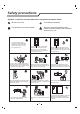
Safety precautions Symbols in this Use and Care Manual are interpreted as shown below. Be sure not to do. Grounding is essential. Pay attention to such a situation. Warning: Incorrect handling could cause a serious hazard, such as death, serious injury, etc. Use correct power supply in accordance with the rating plate requirement. Otherwise, serious faults or hazard may occur or a fire maybe break out. Do not knit, pull or press the power supply cord, lest the power supply cord be broken.
Identification of parts Indoor unit Front Panel Air Intake Display Panel Emergency Panel Air Outlet Vertical Adjustment Louver Horizontal Adjustment Louver ON OF ON MO SW SM ER FA SL IF EE ON TI M ER F FF Air Filter DE IN G AR EE T TI M /O N P SU L DI M O FF CL PE R M ER O CK Remote Controller Air Intake Outdoor unit Pipes and Power Connection Cord Drain Hose Note: Condensate water drains at COOLING or DRY operation.
Display introduction Temperature indicator 1 Display set temperature. It shows FC after 200 hours of usage as reminder to clean the filter. After filter cleaning press the filter reset button located on the indoor unit behind the front panel in order to reset the display.(optional) Running indicator 2 It lights up when the AC is running. It flashes during defrosting. Run Timer indicator Timer 3 It lights up during set time. Sleep indicator Sleep 4 It lights up in sleep mode.
Display introduction TLseries 9 1 3 2 4 Emergency button 10 ON/OFF To let the AC run or stop by pressing the button. 10 The symbols may be different from these models, but the functions are similar.
Maintenance Front panel maintenance Air filter maintenance Cut off the power supply It is necessary to clean the air filter after using it for about 200 hours. Turn off the appliance first before disconnecting from power supply. Clean it as follows: a Stop the appliance and remove the air filter. Grasp position "a" and pull outward to remove the front panel. a 1 2 Wipe with a soft and dry cloth. Use soft moisture cloth to clean if the front panel is very dirty. 3 1.Open the front panel. 2.
Protection Noise pollution Operating condition The protective device maybe trip and stop the appliance in the cases listed below. Install the air conditioner at a place that can bear its weight in order to operate more quietly. Outdoor air temperature is over 24oC Install the outdoor unit at a place where the air discharged and the operation noise would not annoy your neighbors.
Troubleshooting The following cases may not always be a malfunction, please check it before asking for service. Trouble Analysis Does not run If the protector trip or fuse is blown,please wait 3 minutes and start again.The protector device may be preventing unit from working. The batteries in the remote control may be dead Check to see if the appliance is properly plugged in.
Installation instructions Installation diagram Distance from ceiling Distance from wall should be over 50mm should be over 200 mm Distance from the wall should be over 50mm Distance from floor should be over 2500mm.
Installation instructions Select the installation location Location for Installing Indoor Unit Indoor unit Height should Pipe length is 15 meters Max. be less than 5m Where there is no obstacle near the air outlet and air can be easily blown to every corner. Where piping and wall hole can be easily arranged. Keep the required space from the unit to the ceiling and wall according to the installation diagram on previous page. Where the air filter can be easily removed.
Installation instructions Indoor unit installation 1. Installing the Mounting Plate Decide an installing location for the mounting plate according to the indoor unit location and piping direction. Keep the mounting. plate horizontal with a horizontal ruler or dropping line. Drill holes of 32mm in depth on the wall for fixing the plate. Insert the plastic plugs to the hole, fix the mounting plate with tapping screws. Inspect if the mounting plate is well fixed. Then drill a hole for piping.
Installation instructions Piping Joints Thermal Insulation: Wrap the piping joints with thermal insulation materials and then wrap with a vinyl tape. wrapped with vinyl type Thermal insulation Piping Thermal Insulation: Large pipe a. Place the drain hose under the piping. b. Insulation material uses polythene foam over 6mm in thickness. Thermal insulation tube Power cord Note: Drain hose is prepared by user.
Installation instructions 4. Connecting of the Cable Front panel Indoor Unit Connect the power cord to the indoor unit by connecting the wires to the terminals on the control board individually in accordance with the outdoor unit connection. Terminal (inside) Cabinet Note: For some models, it is necessary to remove the cabinet to connect to the indoor unit terminal. Indoor unit Chassis Outdoor Unit 1) Remove the access door from the unit by loosening the screw.
Installation instructions Wiring diagram Make sure that the color of the wires in the outdoor unit and terminal No. are the same as those of the indoor unit.
Installation instructions Outdoor unit installation Rubber pad (optional) Place under the leg pedestal 1. Install Drain Port and Drain Hose (for heat-pump model only) The condensate drains from the outdoor unit when the unit operates in heating mode. In order not to disturb your neighbor and protect the environment, install a drain port and a drain hose to direct the condensate water.
Installation instructions How to Purge Air Tubes: (1) Unscrew and remove caps from 2 and 3-way valves. (2) Unscrew and remove cap from service valve. (3) Connect vacuum pump flexible hose to the service valve. (4) Start vacuum pump for 10-15 minutes until reaching a vacuum of 10 mm Hg absolutes. (5) With vacuum pump still running close the low pressure knob on vacuum pump manifold. Then stop the vacuum pump. (6) Open 2-way valve ,1/4 turn, then close it after 10 seconds.