
Instruction manual

Issue H Oct 04
PAGE
4
GV Dry Vacuum Pumps
INTRODUCTION
4
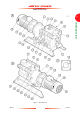
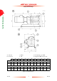
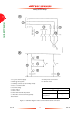
1.6 Drive operation
The pump has a flexible drive coupling which
transmits the drive from the pump-motor (16) to
the pump rotors.
Refer to Figure 12. A coupling hub (14) is fitted to
the pump shaft (9) and a drive hub (16) is fitted to
the motor shaft (18). A coupling insert (15) fits
between the coupling and drive hubs.
The drive hub incorporates a number of drilled
holes. With a coupling cover (12) removed, you can
fit a steel rod (or other suitable tool) to one of these
holes, and you can then manually turn the drive
shaft, and so turn the pump. This facility is useful if,
for example, you need to drain fluid from the pump
following a hydraulic lock (see Table 15).
1.7 Liquid pumping capability
The GV pump can survive the ingress of some liquid
(after a process failure condition, for example)
without damage, however the pump is not suitable
for continuous pumping of liquids.
If you want to continuously pump a liquid stream,
contact your supplier or BOC Edwards for advice.
1.8 Safe area operation
You must not use the GV pump in the following
hazardous areas:
• Zone 0, Zone 1 or Zone 2 (gases), or Zone Z
(10) or Zone Y (11) (dusts), as classified by
European authorities.
• Division 1 or Division 2 (gases and dusts), as
classified by North American authorities.
These hazardous areas require the use of
flameproof equipment. If you need a pump which
can operate in these areas, contact your supplier or
BOC Edwards for advice.
1.9 Accessories
A number of accessories are available for the GV
pumps; use these to configure the pump for specific
applications. These accessories are listed in
Section 7.4.