
Instruction manual

Oct 04 Issue H
GV Dry Vacuum Pumps
PAGE
11
11
INSTALLATION
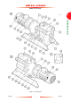
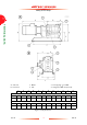
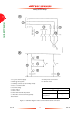
3.5 Check the gearbox oil-level
Refer to Figure 1. The pump is supplied filled with
oil. Before you operate the pump, check that the
gearbox oil-level is correct: the oil-level must be
between the MIN and MAX marks on the bezel of
the oil-level sight-glass (14): see detail C.
If necessary, pour more oil into the gearbox: refer
to Section 5.3.
3.6 Electrical connections
3.6.1 Introduction
Make the electrical connections to the pump as
described in the following sections. Figure 3 shows a
schematic diagram of the recommended electrical
circuit for correct operation and shut-down of the
pump (and closure of an optional pump-inlet
isolation-valve) when the shut-down thermal snap-
switch opens.
We recommend that you connect the electrical
supply to the pump through a suitable current
monitor, and that you configure the high current
setting on the current monitor to switch off the
pump-motor at a suitable overload current.
This overload current must not exceed the
maximum current rating shown on the rating plate
on the pump-motor.
Connect your electrical supply to the pump-motor
through a suitable contactor. The contactor must
incorporate a motor protection circuit-breaker
which meets the full load current ratings specified in
Table 4.
Refer to Figure 1. Note that there are earth
(ground) points in the pump-motor terminal-box
(17) and in the thermal snap-switch box (4).
3.6.2 Connect the electrical supply to the
pump: 380/400/415 V, 50 Hz supplies
Connect the electrical supply from the contactor to
the pump-motor as described below.
1. Remove the cover from the pump-motor
terminal-box (Figure 1, item 16).
2. Remove the plug from one of the electrical
supply cable entry holes on the terminal-box.
3. Fit a suitable cable-gland and nut to the entry
hole, then pass the supply cable through the
cable-gland and tighten the gland. The cable-
gland you use must be rated to provide seal
protection of IP66 (in IEC 529) or better to the
terminal-box .
4. Refer to Figure 4 (page 13). Ensure that the
links (1) are correctly configured on terminals
U1 and W2, V1 and U2, and W1 and V2.
5. Connect the phase conductors (L1, L2, L3) of
the supply cable (4) to terminals U1, V1 and
W1, as shown in Figure 4.
6. Connect the earth (ground) wire to the earth
(ground) terminal (3).
7. Tighten the cable-gland nut strain-relief screws
and refit the terminal-box cover.
WARNING
Ensure that the electrical installation
of the pump conforms with your
local and national safety
requirements. It must be connected
to a suitably fused and protected
electrical supply and a suitable earth
(ground) point.
CAUTION
Ensure that the motor is correctly configured for
your electrical supply voltage and frequency. If you
do not, you can damage the motor.