
Instruction manual

Issue H Oct 04
PAGE
12
GV Dry Vacuum Pumps
INSTALLATION
12
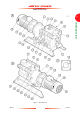
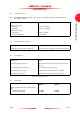
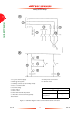
Figure 3 - Schematic diagram of the recommended electrical connections
1. To your electrical supply
2. Earth (ground) points
3. Auxiliary contacts (2 off, normally closed)
4. Fuse or circuit breaker
5. Control voltage
6. Stop control
7. Start control
8. Shut-down thermal snap-switch
9. Inlet-valve control solenoid (optional)
10. Contactor
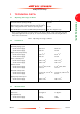
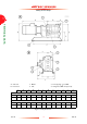
Earth (ground) points
Location Size
Thermal snap-switch box M4 tapped hole
Pump-motor -
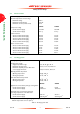
A Pump-motor connections
B Control circuit