
Instruction manual

Oct 04 Issue H
GV Dry Vacuum Pumps
PAGE
15
15
INSTALLATION
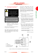
5. Connect the phase conductors (L1, L2, L3) of
the supply cable (1) to terminals T1, T2 and T3.
6. Connect the earth (ground) wire to the earth
(ground) terminal (5).
7. Tighten the cable-gland nut strain-relief screws
and refit the terminal-box cover.
3.6.4 Connect to the thermal snap-
switches
Connect the output of the warning thermal snap-
switch to your control equipment to provide an
indication that the pump is too hot.
You must connect the output of the shut-down
thermal snap-switch to the electrical-overload
control-loop of your contactor, so that the
contactor will automatically switch off the pump if it
is too hot: refer to Figure 3.
WARNING
You must connect the shut-down
thermal snap-switch so that the
pump stops when the thermal snap-
switch opens. If you do not, there
may be a risk of fire or explosion.
WARNING
Incorporate a manual reset device in
your control equipment. If you do
not (and a fault which causes the
shut-down thermal snap-switch to
open is not corrected), the pump will
automatically switch on again when it
cools down. If you have started
maintenance or fault finding on the
pump, there will then be a risk of fire
or explosion and injury to people.
CAUTION
Ensure that you route the thermal snap-switch
cable away from hot surfaces of the pump or other
equipment. If you do not, the cable may be
damaged.
The thermal snap-switches will reset (that is, close
again) when the pump cools down to a preset
temperature (see Section 2.5). We therefore
recommend that your control equipment
incorporates a manual reset device so that the pump
does not automatically switch on again when it cools
down.
Use the following procedure to connect to the
thermal snap-switches. If you connect to the thermal
snap-switches as described below, the output from
the thermal snap-switches will be normally closed
and will open when the pump is too hot.
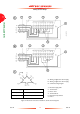
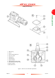
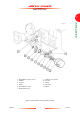
1. Refer to Figure 6 (page 17). Undo and remove
the four screws (1) which secure the cover (2)
to the thermal snap-switch box (3), then
remove the cover.
2. Remove the plastic bag from inside the box,
then open the bag; this bag contains the crimp
connectors and insulators you will use to
connect to the snap-switches.
3. Pass a suitably rated four-core cable through
the cable-gland (5).
4. Fit the crimp connectors to the ends of the four
wires in the cable (4), then fit the insulators
around the connections.
5. Fit the crimp connectors on one pair of wires
(11) to the spade terminals (10) of the shut-
down thermal snap-switch (9).
6. Connect the other ends of the same pair of
wires to the electrical-overload loop of your
contactor.
7. Fit the crimp connectors on the remaining pair
of wires (6) to the spade terminals (7) on the
warning thermal snap-switch (8).
8. Connect the other ends of the same pairs of
wires to the warning circuit of your control
equipment.
9. Tighten the cable-gland (5) to secure the cable
in position.
10. Refit the cover (2) and secure with the four
screws (1).