
Instruction manual

Oct 04 Issue H
GV Dry Vacuum Pumps
PAGE
17
17
INSTALLATION
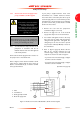
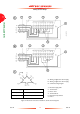
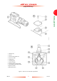
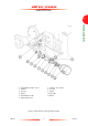
Figure 6 - Connect to the thermal snap-switches
1. Bolts (4 off)
2. Cover
3. Thermal snap-switch box
4. Four-core cable
5. Cable-gland
6. Warning wires
7. Spade terminals
8. Warning thermal snap-switch
9. Shut-down thermal snap-switch
10. Spade terminals
11. Shut-down wires