
Instruction manual

Issue H Oct 04
PAGE
18
GV Dry Vacuum Pumps
INSTALLATION
18
Connect the cooling-water supply as described
below; you must use
1
/
2
inch outside diameter pipes
for the cooling-water supply and return pipelines.
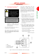
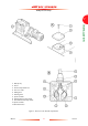
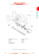
1. Refer to Figure 1. Remove the red blanking caps
from the cooling-water inlet (6) and outlet
compression connections (2).
2. Remove the
1
/
2
inch compression nuts and
ferrules from the fittings kit and fit them finger-
tight onto the cooling-water inlet (6) and outlet
(2) connections.
3. Fit the end of your cooling-water supply
pipeline to the cooling-water inlet compression
fitting (6), then tighten the compression nut to
secure the pipeline in place.
4. Fit the end of your cooling-water return
pipeline to the cooling-water outlet
compression fitting (2), then tighten the
compression nut to secure the pipeline in place.
3.10 Connect the shaft-seals purge and
gas-ballast gas supplies
3.10.1 Introduction
You must determine the correct shaft-seals purge
and gas-ballast requirements for your application.
You must connect nitrogen supplies to the gas
systems if you will pump dangerous gases.
• If required for your application, use the
procedure in Section 3.10.2 to connect a
compressed air supply to the shaft-seals purge
inlet. As supplied, the gas-ballast system can
deliver filtered atmospheric air to the pump
gas-ballast inlet, so you do not need to
connect an air supply to the gas-ballast
system.
• If required for your application, connect
nitrogen supplies to the shaft-seals inlet and
to the gas-ballast system. Use the procedures
in Sections 3.10.2 and 3.10.3 to connect
nitrogen supplies to the shaft-seals purge inlet
and to the gas-ballast system.
3.10.2 Connect the shaft-seals purge air or
nitrogen supply
Note: Your compressed air or nitrogen gas supply
must be clean and dry.
We recommend that you install suitable pressure
control devices, a pressure gauge, and an
automatically operated isolation-valve in your
compressed air or nitrogen supply configured so
that:
• The shaft-seals purge air or nitrogen supply is
on whenever the pump is on.
• If you connect a nitrogen supply, the nitrogen
supply is off whenever the pump is off.
• Whenever the shaft-seals purge air or
nitrogen supply is on, you must maintain the
pressure to the shaft-seals as specified in
Section 2.7.
Use the following procedure to connect your shaft-
seals purge air or nitrogen supply; you must use a
rigid metal (such as stainless steel) pipeline with an
outside diameter of
1
/
4
inch for your air or nitrogen
supply pipeline.
1. Refer to Figure 1. Remove the red blanking cap
from the shaft-seals purge inlet (22).
WARNING
If you will pump dangerous gases, fit a
suitable closed-circuit nitrogen
supply to the shaft-seals purge inlet,
to prevent the escape of dangerous
gases from the pump.
CAUTION
Your compressed air or nitrogen supply pressure
must comply with the requirements of Section 2.7.
If it does not, the shaft-seals purge pipeline may
become over-pressurised and the shaft-seals may
fail.