
Instruction manual

Oct 04 Issue H
GV Dry Vacuum Pumps
PAGE
19
19
INSTALLATION
2. Remove the
1
/
4
inch compression nut and
ferrule from the fittings kit and fit them finger-
tight onto the shaft-seals purge inlet connection
(22).
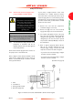
3. Fit the end of your air or nitrogen supply
pipeline to the shaft-seals purge inlet
connection (22), then tighten the nut to secure
the pipeline in place.
3.10.3 Connect a nitrogen gas-ballast supply
(optional)
Notes: Ensure that the gas-ballast nitrogen supply is
clean and dry.
Your nitrogen supply pipeline must terminate
in a KF16 fitting, to enable you to connect it to
the flow valve.
If required for your application, you can connect a
non-venting (to atmosphere) nitrogen gas-ballast
supply to the pump. You must connect a non-
venting (to atmosphere) nitrogen gas-ballast supply
to the pump if you will pump dangerous gases.
When you connect a nitrogen supply to the gas-
ballast system, we recommend that you incorporate
a suitable pressure gauge in the nitrogen supply
pipeline.
Use the following procedure to connect a nitrogen
supply to the gas-ballast system:
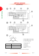
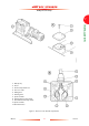
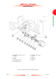
1. Refer to Figure 7. Undo and remove the clamp
(4) and the NW16 trapped ‘O’ ring (3) and
remove the air filter (2).
2. Use the clamp (4) and trapped ‘O’ ring (3) to
connect your nitrogen supply pipeline to the
gas-ballast flow valve (5).
WARNING
If you will pump dangerous gases, fit a
suitable non-venting (to atmosphere)
nitrogen supply to the gas-ballast
system, to prevent the escape of
dangerous gases from the pump.
3.11 Connect the pump-inlet
When you connect the pump to the process system:
• Support process pipelines to stop the
transmission of stress to pipeline joints.
• Use a flexible connection in the pipeline from
the process system to the pump to reduce
vibration and stress in the system pipelines.
Use the following procedure to connect the inlet of
the GV pump to your process system. This
procedure assumes that a mechanical booster pump
has not been fitted. If a mechanical booster pump
has been fitted, use the instructions given in the
appropriate instruction manual supplied with the
mechanical booster pump.
1. Refer to Figure 1. Undo and remove the eight
M8 x 35 hex-head bolts which secure the
blanking-plate to the pump-inlet (6) and remove
the blanking-plate. Retain the bolts.
2. Use the combined trapped ‘O’ ring and mesh
filter supplied to connect the pump-inlet (6) to
your vacuum system; secure with the bolts
retained in Step 1.
Note: If required, you can adapt the blanking-plate
removed in Step 1 above to fit your system
pipelines: drill a suitable size hole in the centre
of the blanking-plate, then weld the blanking-
plate to your pipeline.