Oct 04 Issue H
GV Dry Vacuum Pumps
PAGE
21
21
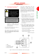
INSTALLATION
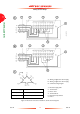
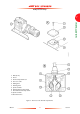
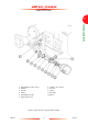
Figure 7 - Exploded view of the gas-ballast assembly
1. Gas-ballast flow valve control
2. Air filter
3. Co-Seal
4. Clamp
5. Gas-ballast flow valve
6. Clamp and Co-Seal
7. Adaptor: 16 to 25 mm
8. Co-Seal
9. Clamp
10. Flap valve
11. Elbow