
Instruction manual


Oct 04 Issue H
GV Dry Vacuum Pumps
PAGE
35
35
MAINTENANCE
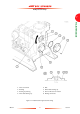
5.10 Replace the interstage relief valve
You must replace the interstage relief valve if it is
damaged. The interstage relief valve is available as a
spare: refer to Section 7.3.
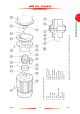
1. Refer to Figure 9. Undo and remove the four
M8 bolts (11) which secure the valve retainer
(9) to the exhaust manifold (3).
2. Place two of the bolts in the jacking holes (10)
and tighten the bolts to remove the retainer (9)
from the exhaust manifold.
3. Remove the 'O' ring (8), valve flap (7), hinge
bushes (1), valve body (2) and 'O' rings (5, 4)
from the exhaust manifold (3).
4. Clean the inside of the exhaust manifold to
remove any deposits; if necessary, use a suitable
cleaning solution. If you use a cleaning solution,
ensure that all of the solution is removed before
you fit the new interstage relief valve.
5. Fit the new interstage relief valve to the exhaust
manifold and secure with the four M8 bolts (11).
Tighten the bolts to a torque of 10 Nm
(7.4 lbf ft).
5.11 Replace the pump-motor
5.11.1 Remove the pump-motor
Use the following procedure to remove the pump-
motor. Ensure that the pump-motor is adequately
supported throughout and does not fall.
WARNING
Ensure that the pump-motor cannot
fall when you remove it. The pump-
motor is heavy and can cause injury
to people if it falls.
The masses of the pump-motors are as shown
below:
1. Refer to Figure 1. Remove the cover from the
pump-motor terminal-box (17) and disconnect
your electrical supply cable from the terminal-
box.
2. Refer to Figure 12. Fit slings and suitable lifting
equipment to support the pump-motor, then
remove the fixing bolts (1) which secure the
pump-motor (19) to the coupling housing (7).
3. Use the lifting equipment to move the pump-
motor (19) away from the pump, then carefully
lower the pump-motor, so that it rests on the
floor in an upright orientation (that is, with the
drive hub (16) at the top).
4. Undo the set screws (3) on the holding ring
(17), then remove the holding ring.
5. Remove the coupling insert (15) and inspect it;
if necessary, replace it.
6. Undo and remove the set screw (4) in the drive
hub (16).
7. Use a suitable puller tool to remove the drive
hub (16) from the motor shaft (18), then
remove the key (2) from the motor shaft.
Dispose of the key.
8. Dispose of the pump-motor: refer to
Section 6.2.
Pump/electrical supply Motor mass
GV250: 380/400/415 V, 50 Hz 104 kg
GV250: 230/460 V, 60 Hz 286 lbs
GV400: 380/400/415 V, 50 Hz 126 kg
GV400: 230/460 V, 60 Hz 364 lbs