
Instruction manual


Issue H Oct 04
PAGE
36
GV Dry Vacuum Pumps
MAINTENANCE
36
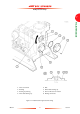
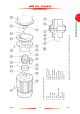
5.11.2 Fit the new pump-motor
1. Refer to Figure 12. Dispose of the key supplied
with the new pump-motor.
2. Inspect the motor shaft (18) of the new pump-
motor (19). The motor shaft must be free of
burrs and dirt. If necessary, clean or refinish the
motor shaft.
3. Inspect the motor shaft bore of the drive hub
(16). The bore must be free of burrs and dirt. If
necessary, clean or refinish the bore.
4. Fit the new key (2, supplied in the Motor
Fitment Kit) into the motor shaft (18).
5. Ensure that the set screw (4) does not protrude
into the bore of the drive hub (16): if necessary,
loosen the set screw.
6. Fit the drive hub (16) fully on the motor shaft
(18). Do not fully tighten the set screw.
7. Ensure that the coupling hub (14) is fully located
on the pump shaft (9), against the shaft bearing
nut (11). If necessary:
• Loosen the set screw (5) in the coupling hub
(14).
• Move the coupling hub so that it is fully on the
pump shaft (9), against the shaft bearing nut
(11).
• Apply a suitable thread sealant (such as
Loctite 242 Nutlock) to the set screw (5),
then fully tighten it.
WARNING
Ensure that the pump-motor does
not fall when you move it. The pump-
motor is heavy (see Section 5.11.1)
and can cause injury to people if it
falls.
CAUTION
Ensure that the pump-motor flange and the
bottom flange of the coupling housing are clean and
free of burrs. If you do not, the pump-motor and
coupling housing may be misaligned and you may
damage the pump-motor, the pump or the drive
coupling when you operate the pump.
8. Slide the holding ring (17) over the coupling hub
(14).
9. Inspect the bottom flange of the coupling
housing (7) and the flange of the pump-motor
(18). The flanges must be free of burrs and dirt.
If necessary, clean or refinish the flanges.
10. Use suitable lifting equipment to lift the pump-
motor off the floor and move it close to the
pump.
11. If necessary, fit slings around the pump-motor
(18) and attach suitable lifting equipment to the
slings. Use both sets of lifting equipment to turn
the pump-motor so that it is horizontal, with
the pump-motor terminal-box at the top, and
with the drive hub (16) towards the coupling
housing (7).
12. Undo and remove the four bolts (13) which
secure one of the coupling covers (12) to the
coupling housing (7), then remove the coupling
cover.
13. Undo and remove the four bolts (13) which
secure the other coupling cover (12) to the
coupling housing (7), then remove the coupling
cover.
14. Move the pump-motor (19) so that the motor
flange locates against the flange of the coupling
housing (7), and so that the bolt holes in the
two flanges are aligned.
15. Use the bolts (1) to secure the pump-motor
(19) to the coupling housing (7).
16. Loosen the set screw (4) on the drive hub (16),
then move the drive hub along the shaft until
the gear teeth on the drive hub (16) and
coupling hub (14) are parallel, and the gap
between the teeth on the two hubs is 2.5 ±
1mm.
(Continued on page 38)