
Instruction manual


Issue H Oct 04
PAGE
38
GV Dry Vacuum Pumps
MAINTENANCE
38
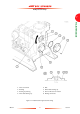
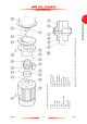
17. Check that the gap (detail A, item 20) is as
shown below.
18. If the gap is not correct:
• Check that the flange of the pump-motor (19)
is correctly located against the flange of the
coupling housing (7).
• If the pump-motor is correctly fitted, loosen
the set screw (7) on the drive hub (16) and
adjust the position of the coupling hub, then
tighten the set screw again. Continue at Step
17 to check that the gap is now set correctly.
19. Apply a suitable thread sealant to the set screw
(4) then fully tighten it to secure the drive hub
(16) to the motor shaft (18).
20. Fit the coupling insert (15) to the gaps between
the teeth on the drive hub (16) and coupling
hub (14).
21. Turn the holding ring (17) so that the reference
line on the holding ring is aligned with the split
in the coupling insert (15), then slide the holding
ring over the insert.
22. Tighten the set screws (3) to secure the holding
ring (17) in place.
23. Ensure that all of the fixing bolts (1) are
tightened to a torque between 128 and 132 Nm
(94 and 97 lbf ft).
24. Use the four bolts (13) to secure one of the
coupling covers (12) to the coupling housing
(7). Tighten the bolts to a torque between 3 and
5 Nm (2.2 and 3.7 lbf ft).
Pump Gap setting
GV250, 50 Hz -1.5 mm *
GV250, 60 Hz -1.5 mm *
GV400, 50 Hz 7.0 mm
GV400, 60 Hz
26.0 mm
* The end of the motor shaft protrudes
beyond the face of the coupling.
25. Use the four bolts (13) to secure the other
coupling covers (12) to the coupling housing
(7). Tighten the bolts to a torque between 3 and
5 Nm (2.2 and 3.7 lbf ft).
5.12 Replace the coupling insert
Use the following procedure to replace the coupling
insert:
1. Refer to Figure 12. Undo the four bolts (13)
which secure one of the coupling covers (12) to
the coupling housing (7), then remove the
coupling cover.
2. Undo the four bolts (13) which secure the
other coupling cover (12) to the coupling
housing (7), then remove the coupling cover.
3. Loosen the set screws (3) on the holding ring
(17), then slide the holding ring off of the
coupling insert (15).
4. Remove the coupling insert (15) and dispose of
it: refer to Section 6.2.
5. Fit the new coupling insert (15) to the gaps
between the teeth on the drive hub (16) and
coupling hub (14).
6. Turn the holding ring (17) so that the reference
line on the holding ring is aligned with the split
in the coupling insert (15), then slide the holding
ring over the insert.
7. Tighten the set screws (3) to secure the holding
ring (17) in place.
8. Use the four bolts (13) to secure one of the
coupling covers (12) to the coupling housing
(7). Tighten the bolts to a torque between 3 and
5 Nm (2.2 and 3.7 lbf ft).
9. Use the four bolts (13) to secure the other
coupling cover (12) to the coupling housing (7).
Tighten the bolts to a torque between 3 and 5
Nm (2.2 and 3.7 lbf ft).