S/M No.TCP850XEF0 Service Manual CHASSIS : CP-850FX MODEL : DTF-2950-100D DTF-2950GB-100D DTF-2950K-100D Caution : In this Manual, some parts can be changed for improving. their performance without notice in the parts list. So, if you need the latest parts information, please refer to PPL(Parts Price List)in Service Information Center. SEP.2006 Downloaded From TV-Manual.
CP-850FX Service Manual CONTENTS DOCUMENT HISTORY .................................................................................................................5 1 MAIN FEATURES...................................................................................................................6 1.1 SPECIFICATIONS ..............................................................................................................6 1.1.1 GENERAL......................................................................
CP-850FX Service Manual 4.4.1.5 German 2-Carrier System (DUAL FM System).........................................................30 4.5 TDA4470 - MULTISTANDARD VIDEO-IF AND QUASI PARALLEL SOUND PROCESSOR .......33 4.5.1 DESCRIPTION ............................................................................................................33 4.5.2 FEATURES..................................................................................................................33 4.5.3 PINNING.........................
CP-850FX Service Manual 5.4.2.4 Black Level Expander/Compressor (BLEC) ..............................................................51 5.4.2.5 Luma Sharpness Enhancer (LSE) ............................................................................51 5.4.2.6 Dynamic Peaking......................................................................................................51 5.4.2.7 Luma Transient Improvement (LTI) ..........................................................................51 5.4.2.
CP-850FX Service Manual 5.10.2.4 Cancellation of OLP Circuit.......................................................................................69 5.10.3 FB Terminal (Pin. 6)...................................................................................................70 5.10.3.1 Constant Voltage Control Circuit.............................................................................70 5.10.4 OCP/BD Terminal (Pin 7)..................................................................................
CP-850FX Service Manual DOCUMENT HISTORY VERSION DATE COMMENTS V1.00 31/07/06 Creation of document (Author JS KIM) for project CP-850FX 100Hz TV. Europe R&D Downloaded From TV-Manual.
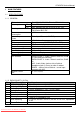
CP-850FX Service Manual 1 MAIN FEATURES 1.1 SPECIFICATIONS 1.1.1 GENERAL TV standard Colour system Sound system Power consumption Sound Output Power Speaker Teletext system Aerial input Channel coverage Tuning system Visual screen size Channel indication Program Selection Aux. terminal PAL/SECAM-B/G, D/K, PAL-I/I, SECAM-L/L’ Tuner PAL, SECAM AV PAL, SECAM, PAL 60, NTSC M, NTSC 4.
CP-850FX Service Manual 10 11 12 13 14 15 16 17 18 19 20 21 N.C. Green Input N.C. Red Earth Blanking Earth Red Input Fast Switching Video Out Earth Video In Earth Video Output Video Input Common Earth 0.7 Vpp ± 0.1V, Impedance 75Ω 0.7 Vpp ± 0.1V, Impedance 75Ω 0 to 0.4V : Logic “0”, 1 to 3V : Logic “1”, Impedance 75Ω 1 Vpp ± 3dB, Impedance 75Ω 1 Vpp ± 3dB, Impedance 75Ω 1.1.
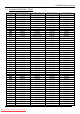
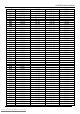
CP-850FX Service Manual 1.2 CHANNEL/FREQUENCY TABLE CHANNEL C01 C02 C03 C04 C05 C06 C07 C08 C09 C10 C11 C12 C13 C14 C15 C16 C17 C18 C19 C20 C21 C22 C23 C24 C25 C26 C27 C28 C29 C30 C31 C32 C33 C34 C35 C36 C37 C38 C39 C40 C41 C42 C43 C44 C45 C46 EUROPE CCIR 46.25 48.25 55.25 62.25 175.25 182.25 189.25 196.25 203.25 210.25 217.25 224.25 53.75 82.25 183.75 192.25 201.25 471.25 479.25 487.25 495.25 503.25 511.25 519.25 527.25 535.25 543.25 551.25 559.25 567.25 575.25 583.25 591.25 599.25 607.25 615.25 623.
CP-850FX Service Manual C47 C48 C49 C50 C51 C52 C53 C54 C55 C56 C57 C58 C59 C60 C61 C62 C63 C64 C65 C66 C67 C68 C69 C70 C71 C72 C73 C74 C75 C76 C77 S01 S02 S03 S04 S05 S06 S07 S08 S09 S10 S11 S12 S13 S14 S15 S16 S17 S18 679.25 687.25 695.25 703.25 711.25 719.25 727.25 735.25 743.25 751.25 759.25 767.25 775.25 783.25 791.25 799.25 807.25 815.25 823.25 831.25 839.25 847.25 855.25 863.25 69.25 76.25 83.25 90.25 97.25 59.25 93.25 105.25 112.25 119.25 126.25 133.25 140.25 147.25 154.25 161.25 168.25 231.25 238.
CP-850FX Service Manual S19 S20 S21 S22 S23 S24 S25 S26 S27 S28 S29 S30 S31 S32 S33 S34 S35 S36 S37 S38 S39 S40 S41 287.25 294.25 303.25 311.25 319.25 327.25 335.25 343.25 351.25 359.25 367.25 375.25 383.25 391.25 399.25 407.25 415.25 423.25 431.25 439.25 447.25 455.25 463.25 Europe R&D Downloaded From TV-Manual.com Manuals 160.00 303.25 311.25 319.25 327.25 335.25 343.25 351.25 359.25 367.25 375.25 383.25 391.25 399.25 407.25 415.25 423.25 431.25 439.25 447.25 455.25 463.25 303.25 311.25 319.25 327.
CP-850FX Service Manual 1.3 ATSS SORTING METHOD The TV set sweeps all the TV bands from beginning of VHF to end of UHF. The TV controlling software for each program checks if a VPS CNI code is transmitted (this system exists for German, Swiss and Austrian transmissions). If no VPS CNI code is found, then the system checks if a CNI code is transmitted as part of the teletext transmission ( Packet 8/30 format 1 and format 2).
CP-850FX Service Manual Note : If two programs with the same name but a different code are found these two programs are listed in group I, II or III . The sorting order within group II, III, and IV is based on the channel frequency. The program with the lowest frequency is allocated the first rank in its group, and so forth until the last program of the group which has the highest frequency.
CP-850FX Service Manual 2 SAFETY INSTRUCTION WARNING: Only competent service personnel may carry out work involving the testing or repair of this equipment. X-RAY RADIATION PRECAUTION 1. Excessive high voltage can produce potentially hazardous X-RAY RADIATION. To avoid such hazards, the high voltage must not exceed the specified limit. The nominal value of the high voltage of this receiver is 25-26 KV (20”-21”) or 26 KV (25” - 28”) at max beam current.
CP-850FX Service Manual 3 3.1 ALIGNMENT INSTRUCTIONS MICROCONTROLLER CONFIGURATION : SERVICE MODE To switch the TV set into service mode please see instruction below. 1 - Select PR. number 91 2 - Adjust sharpness to minimum and exit all menus. 3 – Within 2 seconds press the key sequence : RED - GREEN - menu The software version is displayed beside the word Service, e.g. “SERVICE V1.00”. To exit SERVICE menu press menu key or Std By key. 3.
CP-850FX Service Manual 3.3.1 OPTION 1 1 0 B7 B6 B5 B4 B3 B2 TOP Teletext OFF FASTEXT (FLOF) OFF TUBE 4:3 Headphone Volume/Bal ance control OFF Dolby Virtual OFF SVHS3 disable Headphone Volume/Bal ance control ON Dolby Virtual ON TOP Teletext ON FASTEXT (FLOF) ON TUBE 16:9 B1 SVHS3 enable B0 Tuner options 00 = Philips 01 = not used 10 = ALPS 11 = PARTSNIC 3.3.
CP-850FX Service Manual 3.4 TV SET ALIGNMENT 3.4.1 LOCAL OSCILLATOR ALIGNMENT Tune a colour bar pattern. The frequency of the signal carrier must be accurate ( Max +/- 10KHz deviation from the nominal channel frequency). Find “AFT” item in service mode. Adjust the coil L150 to bring the cursor to central position : 32. 3.4.2 G2 ALIGNMENT - Tune a colour bar pattern. - Find the “G2 – SCREEN” item in service mode. - Adjust screen volume ( on FBT ) to bring the cursor to central position : 32. 3.4.
CP-850FX Service Manual HOR WIDTH adjust for 93% overscan. PARABOLA CORNER B & CORNER T EW TRAPEZ 3.4.8 AGC - Make sure option bits are correct for the tuner fitted on the chassis (See above how to change option bits). - Adjust the antenna signal level at 62 dBμV± 1 - Tune a colour bar pattern. - Find the “AGC” item in service mode. - Press the key “OK” on the remote keypad and wait until AGC level stabilise to the optimum value.
CP-850FX Service Manual 4 4.1 IC DESCRIPTION TELETEXT DECODER WITH EMBEDDED 8-BIT CONTROLLER TVText Pro is a 8-bit controller based on a enhanced 8051 core with embedded teletext, On screen Display and TV controller functions. 4.1.1 BLOCK DIAGRAM OF THE SDA55XX 4.1.
CP-850FX Service Manual interface and receives/transmits data via I 2 C-firmware user-interface. The slicer combined with dedicated hardware stores TTX data in a VBI buffer of 1 Kilobyte. The Microcontroller firmware performs all the acquisition tasks (hamming-and parity-checks, page search and evaluation of header control bits) once per field. Additionally, the firmware can provide high-end Teletextfeatures like Packet-26-handling, FLOF, TOP and list-pages. 4.1.
CP-850FX Service Manual 23 24 25 26 27 28 29 30 31 32 33 34 35 36 37 38 39 40 41 42 43 44 45 46 47 48 49 50 51 52 IR INT n.c. n.c. n.c. n.c. VSS VDD3.3 n.c. n.c. RESET XTAL2 XTAL1 VSSA VDDA2.5 R OUT G OUT B OUT BK OUT VDD2.5 VSS VDD3.3 n.c. n.c. n.c. AGC n.c. n.c. LED POWER Europe R&D Downloaded From TV-Manual.com Manuals IN IN Remote control signal input Interrupt input from audio processor IN IN Ground (0V) Input/Output 3.
CP-850FX Service Manual 4.2 VSP94x5B (version C4)– OPTIMUS Color Decoder and Scan-Rate Converter The VSPB family supports 15/32kHz systems and is available with different options. VSP 94x5B has one channel only. 4.2.1 BLOCK DIAGRAM OF THE VSP94x5B Europe R&D Downloaded From TV-Manual.
CP-850FX Service Manual 4.2.
CP-850FX Service Manual - - z 2D and 3D frames for master and slave channel z Vertical chrominance shift for improved VCR picture quality z Contrast, brightness and saturation control Sharpness improvement z Digital color transition improvement (DCTI) z Adaptive horizontal and vertical peaking (luminance) z Digital luminance transition improvement (DLTI) z Digital contrast improvement (DCI, master channel only) Three D/A converters 9 bit amplitude resolution for YUV, RGB output (Nominal) 72 MHz clock fre
CP-850FX Service Manual 33 34 35 36 37 38 39 40 41 42 43 44 45 46 47 48 49 VSSD4 VDDD4 VDDAFBL VSSAFBL FBL1 FBL2 RIN1 GIN1 BIN1 VDDARGB VDDARGB VDD33RGB VDD33RGB RIN2 GIN2 BIN2 VSSD5 S S S S I I I I I S S S S I I I S 50 VDDAC1 S 51 52 53 54 55 56 57 58 59 60 61 62 63 64 65 66 67 68 69 70 71 72 73 74 75 76 77 78 79 80 VSSAC1 CVBS1 CVBS2 CVBS3 CVBS4 CVBS5 CVBS6 CVBS7 VDD33C VSS33C CVBSO3 CVBSO2 CVBSO1 VDDAC2 VSSAC2 VDDD1 VSSD1 VDDAPLL XOUT XIN TCLK VDDP1 VSSP1 656HIN/CLKF20 VDDDACV AVOUT VSSDACV VDDDAC
CP-850FX Service Manual 4.3 DDP 3315C – DISPLAY AND DEFLECTION PROCESSOR The DDP 3315C is a mixed-signal single-chip digital display and deflection processor, designed for high-quality backend applications in double scan and HDTV TV sets with 4:3 or 16:9 picture tubes. The interfaces qualify the IC to be combined with state of the art digital scan rate converters, as well as analog HDTV sources.
CP-850FX Service Manual – horizontal frequency for VGA/SVGA/1080I – black switch off procedure – supports horizontal and vertical dynamic focus Miscellaneous – selectable ITU-R 601 4:1:1 / 4:2:2 YC r C b input at 27/32 MHz or double scan ITU-R 656 input at 54 MHz line-locked clock – crystal oscillator for horizontal safety – picture frame generator – hardware for simple 50/60 Hz to 100/120 Hz conversion (display frequency doubling) – PQFP80 package, 5 V analog and 3.
CP-850FX Service Manual 4.3.3 PINNING Pin No.
CP-850FX Service Manual 48 49 50 51 52 53 54 55 56 57 58 59 60 61 62 63 64 65 66 67 68 69 70 71 72 73 74 75 76 77 78 79 80 VRD/BCS AGND FBLIN1 RIN1 GIN1 BIN1 FBLIN2 RIN2 / PR GIN2 / Y BIN2/ PB ASG2 HCS NC TEST RESQ SCL SDA C0 C1 C2 C3 C4 C5 C6 C7 VSUPD GNDD Y0 Y1 Y2 Y3 Y4 Y5 I S I I I I I I I I S I I I I/O I/O I I I I I I I I S S I I I I I I Europe R&D Downloaded From TV-Manual.
CP-850FX Service Manual 4.4 MSP341X MULTISTANDARD SOUND PROCESSOR The MSP 341x is designed as a single-chip Multistandard Sound Processor for applications in analogue and digital TV sets, video recorders, and PC cards. The MSP3411 has all functions of MSP3410 with the addition of a virtual surround sound features. Surround sound can be reproduced to a certain extent with two loudspeakers.
CP-850FX Service Manual 4.4.1.2 DSP-Section (Audio Baseband Processing) flexible selection of audio sources to be processed performance of terrestrial de-emphasise systems (FM, NICAM) digitally performed FM-identification decoding and de-matrixing digital baseband processing: volume, bass, treble simple controlling of volume, bass, treble 4.4.1.
CP-850FX Service Manual I D/K 6.0 / 6.552 6.5 / 6.2578125 D/K1 6.5 / 6.7421875 D/K2 6.5 / 5.85 D/K-NICAM FM-Mono / NICAM FM Stereo FM-Mono / NICAM PAL SECAMEast UK USSR Hungary Architecture of MSP341x Pin connections and short description Pin No. Pin Name Type 1 NC 2 NC 3 NC 4 INT Out 5 MUTE Out 6 ADR_SEL In 7 STANDBYQ In 8 NC 9 I2C_CL In / Out 10 I2C_DA In / Out 11 NC 12 NC 13 NC 14 NC 15 NC 16 NC 17 NC 18 DVSUP 19 DVSS 20 NC 21 NC 22 NC Europe R&D Downloaded From TV-Manual.
CP-850FX Service Manual 23 24 25 26 27 28 29 30 31 32 33 34 35 36 37 38 39 40 41 42 43 44 45 46 47 48 49 50 51 52 53 54 55 56 57 58 59 60 61 62 63 64 NC RESETQ DACA_R DACA_L VREF2 DACM_R DACM_L NC NC NC SC2_OUT_R SC2_OUT_L VREF1 SC1_OUT_R SC1_OUT_L CAPL_A AHVSUP CAPL_M AHVSS AGNDC NC NC NC SC3_IN_L SC3_IN_R ASG2 SC2_IN_L SC2_IN_R ASG1 SC1_IN_L SC1_IN_R VREFTOP MONO_IN AVSS AVSUP ANA_IN1+ ANA_IN1NC TESTEN XTAL_IN XTAL_OUT NC Europe R&D Downloaded From TV-Manual.
CP-850FX Service Manual 4.5 TDA4470 - MULTISTANDARD VIDEO-IF AND QUASI PARALLEL SOUND PROCESSOR 4.5.1 DESCRIPTION The TDA4470 is an integrated bipolar circuit for multi-standard video/sound IF (VIF/SIF) signal processing in TV/VCR and multimedia applications. The circuit processes all TV video IF signals with negative modulation (e.g., B/G standard), positive modulation (e.g., L standard) and the AM, FM/NICAM sound IF signals. 4.5.2 FEATURES - 5 V supply voltage; low power consumption.
CP-850FX Service Manual 4.5.4 BLOCK DIAGRAM Europe R&D Downloaded From TV-Manual.
CP-850FX Service Manual 4.6 TDA8946J STEREO AUDIO AMPLIFIER The TDA 8946J is a dual-channel audio power amplifier with an output power of 2 x 15 W at an 8 Ω load and a 18 V supply. The circuit contains two Bridge Tied Load (BTL) amplifiers with an all-NPN output stage and standby/mute logic. The TDA8946J comes in a 17-pin DIL-bentSIL(DBS) power package. The TDA8946J is printed-circuit board compatibel with all other types in the TDA894x family.
CP-850FX Service Manual Block diagram TDA8946J Europe R&D Downloaded From TV-Manual.
CP-850FX Service Manual 4.7 TDA8358J VERTICAL AMPLIFIER The TDA8358J are power circuit for use in 90° and 110° colour deflection systems for field frequencies of 25 to 200Hz field frequencies, and for 4:3 and 16:9 picture tubes. The IC contains a vertical diflection output circuit, operating as a high efficiency class G system. The full bridgeoutput circuit allows DC coupling of the deflection coil in combination with single positive supply voltages.
CP-850FX Service Manual Europe R&D Downloaded From TV-Manual.
CP-850FX Service Manual 4.8 TDA6108JF The TDA6108JF includes three video output amplifiers in one plastic DIL-Bent-SIL 9-pin medium power(DBS9MPF) package(SOT111-1), using high voltage DMOS technology, and is intended to drive the three cathodes of a colour CRT directly. To obtain maximum performance, the amplifier should be used with black-current control. Features Typical bandwidth of 9.
CP-850FX Service Manual Block diagram TDA6108JF 4.9 24C16 - 16 KB EEPROM Features : 16 Kbit serial I2C bus EEPROM Single supply voltage : 4.5 V to 5.5 V 1 Million Erase/Write cycles (minimum) 40 year data retention (minimum) Pin description Pin No. Name 1, 2, 3 E0, E1, E2 5 SDA 6 SCL 7 WC 8 Vcc 4 Vss Description Device address – not used Serial Data/Address Input/Output Serial clock Write control Supply voltage Ground The memory device is compatible with the I2C memory standard.
CP-850FX Service Manual 4.10 STR – W6754 4.10.1 GENERAL DESCRIPTION The STR-W6700 series is a Hybrid IC (HIC) designed for Quasi-Resonant type Switching Mold Power Supply built-in a Power MOSFET and Control IC. 4.10.2 FEATURES operation mode turns blocking oscillation by reducing output voltage at stand-by mode. In addition to the existing Quasi-Resonant Operation, the Bottom-Skip Function is added in order to be efficient from light to medium load.
CP-850FX Service Manual 4.10.4 PIN DESCRIPTION Pin No.
CP-850FX Service Manual 4.10.
CP-850FX Service Manual 5 5.1 CP-850FX CHASSIS DESCRIPTION POWER SUPPLY BLOCK DIAGRAM Europe R&D Downloaded From TV-Manual.
CP-850FX Service Manual 5.2 VIDEO & STEREO AUDIO BLOCK DIAGRAM Europe R&D Downloaded From TV-Manual.
CP-850FX Service Manual 5.3 IF SECTION 5.3.1 BLOCK DIAGRAM Europe R&D Downloaded From TV-Manual.
CP-850FX Service Manual 5.3.2 VISION IF AMPLIFIER The video IF signal (VIF) is fed through a SAW filter to the differential input (Pin 6-7) of the VIF amplifier. This amplifier consists of three AC-coupled amplifier stages. Each differential amplifier is gain controlled by the automatic gain control (VIF-AGC). The output signal of the VIF amplifier is applied to the FPLL carrier generation and the video demodulator. SAW filters Ref.
CP-850FX Service Manual 5.3.5 VIDEO DEMODULATION AND AMPLIFIER The video IF signal, which is applied from the gain controlled IF amplifier, is multiplied with the inphase component of the VCO signal. The video demodulator is designed for low distortion and large bandwidth. The demodulator output signal passes an integrated low pass filter for attenuation of the residual vision carrier and is fed to the video amplifier.
CP-850FX Service Manual and SECAM operation a baseband delay line is used for U and V signals. This can be used as comb filter in NTSC operation (only for chrominance). The RGB input from SCART is used as an overlay for the CVBS channel (RGB+FBL). This block contains a matrix (for RGB signals). 5.4.1.2 Input Selector The analog CVBS or SVHS luma signal are fed to the inputs CVBS1...7 of VSP94x2A (amplitude 0.5...1.5 V pp ). One signal is selected and fed to the first ADC.
CP-850FX Service Manual pixels by subsampling. To prevent the introduction of alias distortion low pass filters are used for luminance and chrominance processing. The horizontal prescaler consists of two main subsampling stages. The first stage is a scaler for rational decimation factors in a range of 1 to 2. The second stage decimates in integer steps (1,2,3,4...32). 5.3.1.8.2 Noise Reduction The structure of the temporal motion adaptive noise reduction is the same for luminance as for chrominance signal.
CP-850FX Service Manual 5.4.2.3 Luma Contrast and Brightness The luminance signal is multiplied by a factor of 0...2 (contrast adjustment). The signal can be shifted by ±100% of its maximal amplitude with the digital brightness value 5.4.2.4 Black Level Expander/Compressor (BLEC) The black level expander/compressor modifies the luminance signal with an adjustable nonlinear function to enhance the contrast of the picture. Dark areas are stretched to black, while bright areas remain unchanged.
CP-850FX Service Manual by over and undershoots at the chroma transition, the sharpened chroma signals are limited to a proper value automatically a) Cr Cb input of CTI b) Cr Cb input + correction signal c) sharpened and limited Cr Cb Europe R&D Downloaded From TV-Manual.
CP-850FX Service Manual 5.4.2.10 Analog Back End The digital RGB signals are converted to analogue RGB by three 10-bit digital to analogue converters (DAC). Each RGB signal has two additional DACs with 9-bit resolution to adjust analogue brightness (40% of the full RGB range) and cutoff / black level (60% of the full RGB range). An additional fixed current is applied for the blanking level.
CP-850FX Service Manual pass filtered with the according gain and time constant. The result is used to attenuate the RGB outputs by adjusting the white drive multipliers for the internal (digital) RGB signals, and the analog contrast multipliers for the analog RGB inputs, respectively. The lower limit of the attenuator is programmable, thus a minimum contrast can always be set. If the minimum contrast is reached, the brightness will be decreased to a programmable minimum as well. 5.4.2.
CP-850FX Service Manual Attenuation Measurement and Compensation Group Delay Measurement and Compensation Exact Decoding of Echo Disturbed Signals 5.5.3 PORTS One 8-bit I/O-port with open drain output and optional I 2 C Bus emulation support (Port 0) Two 8-bit multifunction I/O-ports (Port 1, Port 3) One 4-bit port working as digital or analogue inputs for the ADC (Port 2) One 2-bit I/O-port with secondary functions (P4.2, 4.3, 4.7) 5.5.
CP-850FX Service Manual 5.5.6 AUTOMATIC PICTURE FORMAT SWITCHING When AUTO mode is selected by the user, the television will automatically select the picture format for the user. If the user does not want to accept this selected format, he can always override the setting by use of the ZOOM control on the remote control.
CP-850FX Service Manual 5.5.6.2 SCART Pin 8 Data (Slow Switching) When there is a signal from SCART 1 pin 8 or SCART 2 pin 8 (named the Slow Switching SSW signal) the TV will enter AV mode, unless the user forces another source (which is possible even though slow switching is present). Aspect Ratio 4:3 16:9 Position CENTRE CENTRE Switching Voltage Level HIGH MEDIUM Format Name Tube 16:9 Tube 4:3 4:3 FULL SCREEN FULL SCREEN 16:9 The SCART 1 signal SSW1 has priority over SSW2. 5.5.6.
CP-850FX Service Manual FULL SCREEN 100% 100% PANORAMA (not AUTO) 100% 100% FAVOURITE (not AUTO) 100% to 133% 75% to 100% Picture is displayed filling the full screen (width and height) Picture is displayed filling the full screen (width and height) by incorporating a non-linear horizontal geometrical error Customised picture size Standard 16/9 picture with 576 active lines Used to fit a picture with 4:3 format on a 16:9 screen by stretching the picture geometry at the borders User-definable forma
CP-850FX Service Manual 5.5.7 EXTERNAL SOURCE CONTROL LOGIC The following schematic, illustrates the logic of control for the two SCART connectors. The terms used in the schematic are described below; 1. AUTO represents a situation where the television has self-selected its picture source. This could be when the SCART SLOW SWITCHING pin has gone to a high state, and the AV 1 input is selected without the intervention of the user. 2.
CP-850FX Service Manual 5.5.8 OVER CURRENT PROTECTION In case of overload, the SMPS secondary voltages will drop. The voltage on pin 5 of microcontroller changes Low to High. The controlling software which continuously monitors this voltage will switch the set to stand by mode. To power on the set again the user must switch it off using the main power switch. Appropriate hysteresis guaranty a reliable operation. 5.
CP-850FX Service Manual OSD Language C12 C13 English, French, German, Italian, Spanish, Dutch, Danish, Finnish, Norwegian, Swedish, Greek 0 0 0 0 1 1 1 1 0 0 0 0 1 1 1 1 0 0 0 0 1 1 1 1 0 0 1 1 0 0 1 1 0 0 1 1 0 0 1 1 0 0 1 1 0 0 1 1 Polish, Hungarian, Czech, Slovakian, Rumanian Bulgarian, Russian 5.
CP-850FX Service Manual 5.7.4 NICAM DECODER In case of NICAM - mode, the phase samples are decoded according the DQPSK - coding scheme. The output of this block contains the original NICAM bitstream. 5.7.5 DSP SECTION All audio baseband functions are performed by digital signal processing (DSP). The DSP section controls the source and output selection, and the signals processing. 5.7.
CP-850FX Service Manual 5.8.2 MODE SELECTION The TDA8946J has several functional modes, which can be selected by applying the proper DC voltage to pin MODE. Mute : In this mode the amplifier is DC biased but not operational (no audio output). This allows the input coupling capacitors to be charged to avoid pop-noise. The devices is in mute mode when 2.5 V < VMODE < (Vcc-1.5 V). Operating : In this mode the amplifier is operating normally. The operating mode is activated at VMODE < 0.5 V. 5.
CP-850FX Service Manual 5.10 POWER SUPPLY (STR-W6754) - Functions of Each Terminal 5.10.1 Vcc Terminal (Pin 4) 5.10.1.1 Start-up Circuit The start-up circuit detects Vcc terminal (No.4 pin) voltage, and makes a control IC start and stop. The power supply of the control IC (Vcc terminal input) employs a circuit as shown in Fig.1. At start-up, C3 is charged through a start-up resistor R2.
CP-850FX Service Manual 5.10.1.2 Auxiliary/Drive Winding Control Circuit Operation Start After the control circuit starts its operation, the power 制御回路動作開始 VCC supply is gained by rectifying and smoothing the Aux. Winding Vol. 18 .2V voltage of the auxiliary winding D. (TYP ) 補助巻線電圧 Fig.3 shows the start-up voltage waveform of the Vcc Terminal. The auxiliary winding voltage does 10 .
CP-850FX Service Manual 5.10.1.3 Overvoltage Protection Circuit Where the voltage exceeding 27.5V(TYP) is imposed on between Vcc and GND terminals, the OVP circuit of the control IC starts its operation and turns latch-mode, and the control IC stops its oscillation.
CP-850FX Service Manual 5.10.1.4 Latch Circuit The latch circuit is a circuit that holds the oscillator output low and stops the power supply circuit operation when OVP or OLP circuit operates. The holding current of the latch circuit is 150µA MAX (Ta = 25C) when the Vcc terminal voltage is minus 0.3V to the operation stop. In order to avoid improper operations caused by noises, etc.
CP-850FX Service Manual 5.10.2.2 Overload Protection The output characteristics of the secondary side at the time 出力電圧 Vout Vou t when the OCP circuit operates, due to the overload of the secondary side output, is shown in Fig.8. Where the output voltage falls below the overload mode, the auxiliary winding AC High AC高 低 A C voltage of the primary side also falls proportionally, and the AC Low Vcc terminal voltage falls below shutdown voltage to stop the operation.
CP-850FX Service Manual The time until the latch protection operation starts its operation can be calculated from the following formula since the ISSOLP(OLP) is a constant current circuit. That is, C (Condenser Capacity) x ⊿V(Condenser Charging Voltage: approx. 5V) = ISSOLP (OLP) x t (time) …… (2) While, the ISSOLP(OLP) contains the voltage dependent characteristics on SS/OLP terminal voltage, and ISSOLP(OLP) falls when SS/OLP terminal voltage rises.
CP-850FX Service Manual 5.10.3 FB Terminal (Pin. 6) The operation of FB terminal is divided into normal (constant voltage control circuit operation) and stand-by operation control. Refer to item No. 8.6 for the controlling at stand-by operation. 5.10.3.1 Constant Voltage Control Circuit The STR-W6700 series adopts the current mode controlling circuit for the constant voltage control, which proves its superiority in a heavy load.
CP-850FX Service Manual 5.10.4 OCP/BD Terminal (Pin 7) The functions of OCP/BD terminal are categorized as Overcurrent Protection (OCP), BottomSkip, and Quasi-Resonant Operation control. Refer to item No. 8.5 for Bottom-Skip and QuasiResonant operation. 8.4.1. Minus-Detection Type OCP Circuit P D LOG IC 1 DRIVE 3 S/GND Filter RB1 + OCP R5[ROCP] Reg.
CP-850FX Service Manual 5.10.5 Quasi-Resonant and Bottom-Skip Operation 5.10.5.1 Quasi-Resonant Operation The Quasi-Resonant operation is to match the timing of the MOSFET Turn-ON to the bottom point of the voltage resonant waveform after a transformer releases the energy (i.e., 1/2 cycle of the resonant-frequency). As shown in Fig.
CP-850FX Service Manual 5.10.5.2 Bottom-Skip Operation (Switching from Quasi-Resonant Operation) The basic bottom-skip operation is that the load of the secondary side is detected by the drain current value (actually OCP/BD terminal voltage), which switches to the Quasi-Resonant (at heavy load) and the Bottom-Skip operation (at light load). The timing of distinguishing is made by taking the OCP/BD terminal voltage in at start-down of the MOSFET gate voltage of the HIC.
CP-850FX Service Manual rating, and the standard voltage is automatically changed to VOCPBD(BS2). Besides, the VOCP is OCP/BD terminal voltage at that time when the MOSFET gate voltage starts down. As described above, the standard voltage (VOCPBD(BS1), VOCPBD(BS2)) realizing the BottomSkip operation provides the hysteresis operation automatically and makes it possible to have the stabilized operation. Fig.17 shows the above operation switching changing mode. 5.10.
CP-850FX Service Manual continues falling because the HIC’s oscillation is suspended until the Vcc terminal voltage (Pin 4) reaches the operation start-up voltage 18V (TYP). Thus it is required to secure the voltage exceeding the required output voltage of secondary side.
CP-850FX Service Manual At the stand-by mode, as mentioned above, due to the burst-mode of the HIC’s intermittent operation, the output voltage falls since the HIC stops its operation during the oscillation stop period. While, during the stand-by operation, the intermittent operation repeating oscillation and stop through the start-up resistor is provided because the transformer’s auxiliary winding voltage supplying the power supply to the HIC is extremely decreased.
CP-850FX Service Manual 6 SERVICE PARTS LIST Caution:In this Service Manual, some parts can be changed for imroving, their performance without notice in the parts list. So, If you need the latest parts information, please refer to PPL(Parts Price List)in Service information Center(http://svc.dwe.co.kr) Important Safety Notice Components Identified by mark have special characteristics inportant for safety. When replacing any of these components, use only manufacturers specified parts.
CP-850/F Service Manual LOC PART CODE PART NAME C604 C805 CEXF1E102V CEYD2G181D C ELECTRO C ELECTRO 25V RSS 1000MF (13X20) TP 400V FHS 180MF C812 C813 C814 C820 C823 C840 C861 C899 CP01 CP02 CP04 CP07 D401 D404 D404A D404B D406 D820 D860 D870 I301 I301A I301B I601 I602 I602A I602B I701 I702 I801 I801A I801B CH1BFE472M CEXF2E101V CEYF2E470V CCXR3D221K CEXF1E222V CEXF1C102V CEXF1E102C CMXF2J333J CMYF2G224J CMXE2J222J CEXF1H221V CMYF2J154J DDTV1500MD DFMP3FU—4857027603 7174301051 DRGP30J—DRGP30J—DRGP30
CP-850/F Service Manual LOC PART CODE PART NAME E58 E6 E62 E63 E7 E8 E9 ZZ200 CC01 CC02 CC03 CC04 CC05 CC06 CC07 CC08 CC10 CC101 CC103 CC110 CC115 CC117 CC119 CC127 CC129 CC13 CC136 CC14 CC15 CC158 CC16 CC160 CC166 CC17 CC177 CC18 CC19 CC501 CC502 CC503 CC504 CC505 CC506 CC507 CC508 CC509 CC511 CC512 CC513 CC514 CC515 CC516 CC517 CC518 CC521 CC522 CC523 CC524 CC526 CC527 CC528 CC549 CC550 CC551 CC552 CC553 CC556 CC560 CC561 CC567 CC568 4856310300 4856310600 4856310300 4856310300 4856310600 4856310300 48
CP-850/F Service Manual LOC PART CODE PART NAME RC580 RC581 RC582 RC583 RC584 RC585 RC586 RC587 RC589 RC591 RC595 RC598 RC611 RC661 RC662 RC701 RC708 RC715 RC716 RC725 RC729 RC730 RC731 RC732 RC733 RC737 RC738 RC739 RC740 RC741 RC742 RC743 RC750 RC770 RC799 RC881 RC882 ZZ200 C102 C106 C117 C118 C120 C121 C150 C152 C153 C157 C164 C188 C301 C305 C313 C320 C340 C350 C351 C370 C401 C410 C416 C417 C420 C424 C425 C501 C502 C503 C504 C505 C506 HRFT821JBA HRFT102JBA HRFT102JBA HRFT102JBA HRFT821JBA HRFT911JBA H
CP-850/F Service Manual LOC PART CODE PART NAME L802 Q103 Q104 Q110 Q150 Q151 Q333 Q334 Q402 Q502 Q503 Q504 Q542 Q543 Q544 Q550 Q601 Q602 Q603 Q604 Q605 Q730 Q731 Q809 Q810 Q812 QP01 QP02 R331 R332 R401 R402 R410 R415 RP04 RP05 RP14 X502 X701 Z601 Z602 Z603 Z604 Z605 Z606 Z607 Z608 ZZ200 10 20 A001 C101 C111 C112 C161 C414 C440 C508 C509 C510 C515 C516 C517 C518 C519 C532 C534 C536 C537 C538 C540 58CX430599 T2SC5343YT2SC5343YT2SC5343YT2SC5343YT2SC5343YT2SC5343YT2SC5343YT2SD1207TT2SC5343YT2SC5343YT2SA198
CP-850/F Service Manual LOC PART CODE PART NAME J234 J235 J236 J240 J243 J276 J278 J28 J287 J289 J30 J300 J301 J303 J305 J306 J307 J308 J31 J310 J311 J32 J320 J322 J324 J325 J327 J328 J33 J335 J336 J337 J339 J34 J340 J341 J342 J344 J345 J347 J348 J35 J350 J351 J353 J354 J355 J356 J357 J358 J359 J36 J362 J363 J365 J366 J367 J368 J369 J37 J371 J373 J374 J375 J377 J378 J379 J38 85801060GY 85801060GY 85801060GY 85801060GY 85801060GY 85801060GY 85801060GY 85801060GY 85801060GY 85801060GY 85801060GY 5MC00001
CP-850/F Service Manual LOC PART CODE PART NAME DESCRIPTION J63 L105 L153 L402 L501 L502 L506 L507 L524 L551 L568 L601 L602 L603 L605 L650 L709 L711 L713 L730 L737 L742 L744 L801 R103 R110 R150 R152 R153 R154 R155 R161 R162 R163 R177 R301 R310 R311 R333 R334 R340 R341 R345 R350 R351 R370 R394 R395 R396 R397 R414 R420 R424 R430 R440 R501 R502 R504 R507 R510 R511 R512 R513 R514 R515 R516 R517 R518 85801060GY 5CPZ479K02 5CPZ120K02 85801060GY 5CPZ479K04 5CPZ479K04 5CPZ479K04 5CPZ100K04 5CPZ100K02 5CPZ479K
CP-850FX Service Manual LOC PART CODE PART NAME R811 R817 R818 R820 R821 R823 R827 R828 R829 R830 R831 R832 R834 R870 R883 R884 RA01 RA10 RA13 RA15 RA16 RA32 RA35 RA88 RP03 RP06 RP08 RP10 RP12 RP13 ZZ400 C900 C910 C997 I901 I901A I901B P401A P501A P903 R906 RC-2Z565KP RD-AZ473JRD-AZ683JRD-4Z363JRD-AZ563JRD-4Z332JRD-AZ103JRD-4Z153JRD-AZ103JRD-AZ101JRD-AZ472JRD-AZ473JRD-4Z470JRD-4Z102JRD-AZ103JRD-AZ103JRD-AZ220JRD-AZ103JRD-AZ332JRD-AZ680JRD-AZ750J85801060GY RD-AZ750JRD-AZ750JRD-4Z102JRD-4Z472JRD-4Z361JRD
CP-850FX Service Manual 7. EXPLODED VIEW Europe R&D Downloaded From TV-Manual.
CP-850FX Service Manual 8. PRINTED CIRCULT BOARD 8.1 MAIN PCB Europe R&D Downloaded From TV-Manual.
CP-850FX Service Manual PRINTED CIRCULT BOARD 8.2 UNION PCB Europe R&D Downloaded From TV-Manual.
CP-850FX Service Manual PRINTED CIRCULT BOARD 8.3 CRT PCB Europe R&D Downloaded From TV-Manual.
CP-850FX Service Manual 9. SCHEMATIC DIAGRAM 9.1 MAIN Europe R&D Downloaded From TV-Manual.
CP-850FX Service Manual 9.2 UNION & CRT Europe R&D Downloaded From TV-Manual.
DAEWOO ELECTRONICS CORP. 686, AHYEON-DONG, MAPO-GU, SEOUL, KOREA. C.P.O. BOX 8003 SEOUL KOREA PRINTED DATE : SEP. 2006 Downloaded From TV-Manual.