Manual de servicio Acondicionador de Aire Tipo Ventana Modelo: DWC-121C/121CS DWC-124C/124CS DWA-121C/121CS DWA-122C/122CS DWA-124C/124CS DWB-121C/121CS DWB-122C/122CS DWB-124C/124CS DWB-123C/123CS DWA-150C/150CS DWA-151C/151CS DWA-152C/152CS
TABLE OF CONTENTS 1. PRECAUTION. . . . . . . . . . . . . . . . . . . . . . . . . . . . . . . . . . . . . . . . . . . . . . . . . . . . . . . . . . . . . . . . . . . . . . . . . . . . . . . 2 2. GENERAL SPECIFICATIONS . . . . . . . . . . . . . . . . . . . . . . . . . . . . . . . . . . . . . . . . . . . . . . . . . . . . . . . . . . . . . . . . 3 3. NAMES OF MAJOR COMPONENTS. . . . . . . . . . . . . . . . . . . . . . . . . . . . . . . . . . . . . . . . . . . . . . . . . . . . . . . 4~5 4.
1. PRECAUTION Please observe the following instructions. 1. Turn off unit. Make sure the unit is OFF and the AC cord is unplugged before repairing or servicing. 2. In case of checking the circuit unavoidably while the unit is connected with power source, be careful not to connect with the part of electric charge. You may cause electric shock. 3. Use of proper part if you need to replace the part, be sure to use genuine part of servicing model. Do not repair or replace the electric contact part.
2.
3.
• DW✽-124C / DWA-152C 0 3 3 2 q 7 7 2 4 4 w 8 8 1 1 5 6 9 5 6 9 • DW✽-124CS / DWA-152CS 0 3 3 2 q 7 7 2 4 4 w 8 8 1 1 5 6 9 5 6 e 9 e NO PART NAME NO 1 AIR FILTER 8 AIR VENT 2 GRILLE 9 FRAME GRILLE 3 CABINET 10 FRAME GUIDE TOP 4 BLADE VERTICAL 11 FRAME WINDOW KIT 5 KNOB THERMOSTAT 12 SHUTTER WINDOW 6 KNOB SELECTOR 13 AUTO LOUVER S/W (DW✽-124CS/DWA-152CS) 7 BLADE HORIZENTAL NOTE: ✽→A or B or C 5 PART NAME
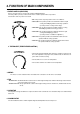
4. FUNCTION OF MAIN COMPONENTS 1. ROTARY SWITCH (SELECTOR) Please refer to the part of selector in the chapter 9 (Wiring Diagram). The rotary switch (selector) controls the fan motor’s rotation speed, and has six positions. The function of the six position is as follow. • OFF: This position stops all operations of the air conditioner. • HIGH COOL: This position provides the maximum air flow for rapid cooling, dehumidifying and dust removing operations. (Use this position on sultry summer days.
5. GENERAL INFORMATIONS 1. CHANGING AIR FLOW DIRECTION Air flow deflectors divert air from center flow to left or right and up or down. Adjust deflectors for desired air flow pattern. 2. AIR FLOW AROUND UNIT Check in door grill and outdoor louvers for air flow obstructions. Do not block air flow to and from unit. The outdoor coil should be checked and periodically cleaned for debris that may collect and block unit air flow.
6. CARE AND MAINTENANCE 1. AIR FILTER Clean the air filter, which removes dust inside the room. It should be washed at least once every week during operation. • All models except DW*-124C/CS, DWA-152C/CS (✽→A or B or C) 1. Remove the Air Filter from the front grill by pulling to right. 2. Clean Air Filter with a vacuum cleaner or lukewarm, soapy water. 3. Shake it when clean to remove moisture completely. Reinstall. • Only DW*-124C/CS, DWA-152C/CS (✽→A or B or C) 1.
7. TROUBLE SHOOTING GUIDE TROUBLE Fan motor and compressor do not run SITUATION 1. Power failure ANALYSIS CAUSE REMEDY 1) Power plug 1) Power failure • Consult your electric company 2) Circuit breaker 2) Circuit breaker is tripped • In case of a breaker, turn it on and off a few times 3) Power plug is not contacting • Replace the power plug 2.
TROUBLE SITUATION CAUSE Not cooling at all Insufficient cooling REMEDY • Blocked by others • Repair • Disconnection or burned-out electric cord • Replace the fan motor • Failure malfunction of contact • Replace • Disconnection of malfunction of contact • Check the circuit 1) Refrigerant system is choked • Repair 2) Compressor failure • Repair 3) Leakage of refrigerant gas • Recharge refrigerant gas 1) Refrigerant system 1) Refrigerant system is choked • Check and repair refrigerant sys
8. HOW TO DISASSEMBLE Please refer to the chapter 11 (Exploded diagram and parts list). (NOTE: ✽→A or B or C) 1 Before service of any part. 2 Ass’y Fan Motor - Fan Motor - Propeller Fan - Blower Fan 1. Stop the unit, remove the power cord from the receptacles. 2. Move the unit to the safe location for the suitable work. • Only DW*-124C/CS, DWA-152C/CS 1. Remove Front Grille - Open the grille upward by pulling out the bottom of the grille, lift it. - Remove screw which fasten Frame Grille with driver.
• HOW TO REMOVE THE FRONT GRILLE FOR ALL MODELS EXCEPT DW✽-124C/CS, DWA-152C/CS ;;;; ;;;;; ;;;;;;;;; ;;;;;;;;; ;;;; ;;;;; ;;;; ;;;;; ;;;;;;;;; ;;;; ;;;;; ;;;; ;;;;; ;;;; ;;;;; ;;;;;;;;; ;;;; ;;;;; ;;;; ;;;;; 1. Pull the Air-filter out of the Front Grille. 2. Loosen screw which fasten Front Grille with driver. 3. Pull knobs out of the control. (when the knobs are too tight to release, leave them.) 4. Disassemble Front Grille from Chassis. – Front Grille and chassis are fixed with snap-fit.
• HOW TO REMOVE THE FRONT GRILLE FOR ONLY DW✽-124C/CS, DWA-152C/CS 1. Open the grille upward by pulling out the bottom of the grille, lift it. 2. Remove screw which fasten Frame Grille with driver. 3. Pull knobs out of the control. (when the knobs are too tight to release, leave them.) 4. Disassemble Frame Grille from Chassis. – Frame Grille and chassis are fixed with snap-fit. 1) Release right-lower snap-fit.
9. WIRING DIAGRAM • DW✻-121C / 122C / 123C / 124C / 150C / 151C / 152C WIRING DIAGRAM (3103523900) SELECTOR SWITCH HIGH MED LOW LOW MED OFF COOL COOL COOL FAN FAN 1 GRN(GRN/YEL) WHT(BLU) 7 6 YEL 4 RED 8 GRY 2 BLU THERMOSTAT SWITCH BLK(BRN) O.L.
10.
11. EXPLODED DIAGRAM AND PARTS LIST. ■ DWA-121C/CS,DWA-122C/CS(124C/CS),DWB-121C/CS,DWB-122C/CS(124C/CS),DWB-123C/CS, DWC-121C/CS(124C/CS), DWA-150C/CS,DWA-151C/CS(152C/CS) PARTS LIST ✔ Caution: In this Service Manual, some parts can be changed for improving, their performance without notice in the parts list. So, if you need the latest parts information, please refer to PPL(Parts Price List) in Service information Center(http://svc.dwe.co.
NO CODE COMPONENTS Q'TY SPECIFICATION REMARK 3104425820 PIPE DISCHARGE 1 C1220T-O OD7.94 DWA,B-122C/CS,123C/CS,124C/CS(ONLY) 3104425810 PIPE DISCHARGE 1 C1220T-O OD7.94 DWA-150C/CS(ONLY) 3104425830 PIPE DISCHARGE 1 C1220T-O OD7.
NO CODE 38 3106700400 CAM 1 POM DW*-121CS,122CS,123CS,124CS,150CS,151CS,152CS(ONLY) 39 5S10405620 S/W ROCKER 1 R19A-2(250VAC6A) DW*-121CS,122CS,123CS,124CS,150CS,151CS,152CS(ONLY) 40 3107000100 CLIP THERMO 1 ABS 41 5S0101800 THERMOSTAT AS 1 PFA-602GF-02(PCC) 42 5S10405100 SWITCH ROTARY 1 SR6B-416-10D 3101300300 POWER CORD 1 KKP-30B,13A 125V DWC-121C/CS,124C/CS(ONLY) 3103001600 POWER CORD 1 WS-001I 250V 13A DWA-121C/CS,122C/CS,124C/CS,150C/CS,151C/CS,152C/CS(ONLY) 31013
■ DWA-121C/CS, DWA-122C/CS, DWB-121C/CS, DWB-122C/CS, DWB-123C/CS, DWC
C/CS, DWA-151C/CS EXPLODED DIAGRAM
■ DW✻-124C/CS, DWA-152C/CS EXPLODED DIAGRAM (NOTE: ✻ →A or B or C)
DAEWOO ELECTRONICS CO., LTD. 686, AHYEON-DONG MAPO-GU SEOUL, KOREA C.P.O. BOX 8003 SEOUL, KOREA TELEX: DWELEC K28177-8 CABLE: “DAEWOOELEC” FAX: 02) 590-6291 TEL: 02) 360-7114/590-6151~5 http://www.dwe. daewoo.co.kr S/M NO.: DWC121C040 PRINTED DATE: APR.