Service Manual Window Type Room Air Conditioner Model: DWC-104R DWC-125R DWA-125R DWA-145R ✔ Caution : In this Manual, some parts can be changed for improving, their performance without notice in the parts list. So, if you need the latest parts information,please refer to PPL(Parts Price List) in Service Information Center (http://svc.dwe.co.kr). DAEWOO ELECTRONICS CORP.
Contents CONTENTS 1. Specifications ................................................................................................2 2. Operation .....................................................................................................3 3. Wiring Diagram..........................................................................................10 4. Refrigerant Cycle .........................................................................................11 5. Control Block Diagram..............
1. SPECIFICATIONS MODEL ITEM DWC-104R DWC-125R Function Energy Efficiency Ratio Dehumidification DWA-145R Cooling only Power source Cooling Capacity DWA-125R AC 115V, 60Hz AC 208~230V, 60Hz Btu/h 10,000 12,100 12,000 14,000 Kcal/h 2,520 3,049 3,024 3,528 Btu/Wh 10.0 10.1 10.1 10.0 Kcal/Wh 2.50 2.54 2.55 2.47 Pts/h 3.17 3.40 2.45 3.93 g/h 1,441 1,545 1,114 1,786 Power Input (W) 1,000 1,200 1,190 1,420 8.6 11.5 5.3 6.
2.
2 REMOTE CONTROLLER REMOCON SIGNAL TRANSMITTER TIMER/CANCEL • Everytime you push this button, timer is set as follow. (1Hr→2Hr→3Hr→4Hr→5Hr→6Hr→8 Hr→10Hr→12Hr→16Hr→20Hr→24Hr →CANCEL). After the unit is timed, if this button is pushed, timer is canceled. TIMER/ CANCEL FAN SPEED SLEEP • SLEEP mode is selected as follow. (L1→L2→Cancel) SLEEP AUTO SWING FAN SPEED • Everytime you push this button, it is selected as follow.
3 REMOTE CONTROLLER DISPLAY MODE DISPLAY • It displays the operating mode. TEMP./TIMER DISPLAY • It displays the temperature and the timer. REMOTE SIGNAL RECEIVER TEMPERATURE SET • It is the button to set the desired room temperature. The temperature can be set within a range from 16°C (60°F) to 32°C (90°F) by 1°C (1°F) SENSOR Room Air-conditioner Fan TEMP Turbo Cooling MODE Timer FAN SPEED AUTO SWING FAN SPEED • Everytime you push this button, It is selected as follow.
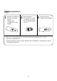
Replacing Batteries 1 Remove the COVER from the back of the remote controller. • Slide the cover according to the arrow direction 2 Insert two battaries. • Be sure that the (+) and (–) directions are correct • Be sure that both batteries are new – + 3 Re-attach the cover. • Slide it back into position + – • Do not use rechargeable batteries such batteries differ from standard dry cells in shape, dimensions and performance.
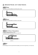
4 DESCRIPTION OF FUNCTIONS OFF-Timer If you set time in OFF-Timer Mode, the unit will stop at the set time. ON Unit ON Unit OFF OFF SET Time HOUR ON-Timer If you set time in ON-Timer Mode, the unit will run at the set time.
Fan Speed (1) Motor speed (low speed, mid speed, high speed). (2) Remote controller setting fan speed. (L, M, H) (3) Relation of operating mode between fan speed. FAN ONLY COOL TURBO H H H H M M M - L L L - Sleep Mode (1) When you are going to sleep, select sleep button in remocon and the unit controls the room to the desired temperature. (The unit will not operate after 4 hour) (2) For changing the temperature.
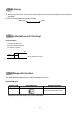
Auto Swing (1) When you push this button, in remocon the left/right flap move to the position of keeping the room temperature comiortable. (2) The air discharge direction procedure is below. Auto swing Fixed Turbo Mode(Powerful Cooling) Cooling Condition 1 Fan Speed: High speed 2 Set temperature:16˚C(Fixed) 3 Compressor and Fan ON OFF (Room temperature-16˚C) -2 0 Self-Diagnostic Function The control will contain diagnostic test to verify the integrity of the system.
3.
4. REFRIGERANT CYCLE Evaporator Blower fan Accumulator M Capillary tube MOTOR Compressor Propeller fan Condenser Model Name Contents Capillary tube Charge Quantity DWC-104R DWC-125R DWA-125R DWA-145R ID 1.4Ø x L800 ID 1.6Ø x L800 ID 1.6Ø x L800 ID 1.
5.
6.
✔ Caution: In this Service Manual, some parts can be changed for improving, their performance without notice in the parts list. So, if you need the latest parts information, please refer to PPL(Parts Price List) in Service information Center(http://svc.dwe.co.kr) Part List ● MAIN PCB AS PART LIST (3114306200) LOC.
✔ Caution: In this Service Manual, some parts can be changed for improving, their performance without notice in the parts list. So, if you need the latest parts information, please refer to PPL(Parts Price List) in Service information Center(http://svc.dwe.co.kr) LOC. CODE PART NAME SPEC QTY RL2 5SC0101310 RELAY US11-12S 1 RL3 5SC0101310 RELAY US11-12S 1 RL4 5SC0101310 RELAY US11-12S 1 RL5 5SC0101310 RELAY US11-12S 1 PCB 3114306210 PCB MAIN 80X130X1.
✔ Caution: In this Service Manual, some parts can be changed for improving, their performance without notice in the parts list. So, if you need the latest parts information, please refer to PPL(Parts Price List) in Service information Center(http://svc.dwe.co.
7. TROUBLE SHOOTING Self-Diagnostic Function Error Code 1(Er) 1 Check the connector of room air thermistor. (or connecting wire) 2 Check soldering of connecting on control P.C.B. (Error of soldering or short) 3 Check the resistance of room air thermistor. “Press the temperature Keys (Up & Down), Error code is displayed.” Unit Not Run The power is applied to the unit Rating voltage Check the voltage between “CN1” and “RL1(N)” of Main P.C.
Only Compressor Do not Run - Check the following at cooling mode Check the voltage between “CN1” and “RL1(COMP)” of Main P.C.B Rating voltage less than 90% Check the Main P.C.B the circuit for relay driving. Rating voltage more than 90% Rating voltage less than 90% Check the compressor wiring Check the connecting wire between Main P.C.
PCB DRIVING DESCRIPTION
1. Power Supply Circuit DC 12V and DC 5V Power source circuit. Diode D4~D7 : Rectifier Diodes Condenser CE1 and CE2 : Smoothing circuit components. DC 12V Power output is made by switching performance of Device IC2 and TRS1. DC 12V Power is used for Relay and Buzzer driving. DC 5V is regulated by IC1. It is used for LED display, Sensor, Key and Micom driving. Regulation of DC12V is performed by PC1 and its voltage feedback signal. And the others are generally used for noise consumption. 2.
3. Sensor Signal Input Circuit and Option Port 4 of IC4 is terminal of A/D converter input. Room temperature is sensing by change of temperature resistance. The input voltage is determined by ratio between R8 (10.0 KΩ) and Room sensor value. Relation between temperature and input voltage is as following. Temperature (°C) Sensor resistance (KΩ) Input Voltage (V) -5 43.67 0.932 0 33.40 1.152 5 25.79 1.397 10 20.10 1.661 15 15.80 1.938 20 12.52 2.220 25 10.00 2.500 30 8.05 2.
4. Display drive and Key Input Circuit Display operation is dynamic scan drive type. It has 1/3 duty cycle. Scan signal output : Port 21, Port 22, Port 23 TR1~TR6 : Scan signal drive circuit R1~R7 : LED current limit resistance .(for 6 high current output port 12,13,15,16,17,18) Port 19, Port 24 of IC4 : Key signal input by scan. Oscillatory frequency is 8MHz. It is made up resonator oscillatory frequency. Oscillatory wave is sine wave shape. The remote control signal input is detacted at port 5 of IC4.
5. Relay and Buzzer drive Circuit Port 6,7,9 of IC4 : Relay ON and OFF drive signal output. IC3 : Relay ON and OFF drive device. Fan Motor ON/OFF and Speed control : RL2, RL3, RL4 Compressor ON/OFF control : RL1. Swing Motor ON/OFF control : RL5 Buzzer is operated by Port 26 of IC4. Operative frequency is 2 KHz, 1/2 duty pulse.
8.
(3) U2(TD62004AP) DARLINGTON ARRAYS IN1 1 IN2 2 IN3 3 IN4 4 IN5 5 IN6 6 IN7 7 GND 8 KID65004AP 16 OUT 1 15 OUT 2 14 OUT 3 13 OUT 4 12 OUT 5 11 OUT 6 10 OUT 7 9 COMMON FREE WHEELING DIODES COM 10.5K 7.2K 3K (Equivalent Circuit) (Top View) (4) U7 (7805CT): VOLTAGE REGULATOR (5VDC) TSUFFIX PLAASTIC PACKAGE CASE 221A TO-220TYPE SCHEMATIC DIAGRAM INPUT 100K 500 100 100 10K 240 200 3.3 K 1 2 3 Pin 1. INPUT 2. GROUND 3. OUTPUT 1.4 K OUTPUT 2K 6K 2.7 K 0.3 0.
9. DISASSEMBLY INSTRUCTIONS Please refer to the chapter 10 (Exploded diagram and parts list). 1 2 Before service of 1. Stop the unit, remove the power cord from the receptacles. any part. 2. Move the unit to the safe location for the suitable work. Ass’y Fan Motor 1. Remove Front Grille - Fan Motor - Open the grille upward by pulling out the bottom of the grille, lift it. - Propeller Fan - Remove screw which fasten Frame Grille with driver. - Blower Fan - Disassemble Frame Grille from chassis.
10. EXPLODED DIAGRAM AND PARTS LIST ✔ Caution: In this Service Manual, some parts can be changed for improving, their performance without notice in the parts list. So, if you need the latest parts information, please refer to PPL(Parts Price List) in Service information Center(http://svc.dwe.co.kr) ■ DWC-104R,DWC-125R PARTS LIST No. CODE 1 3112200400 FRAME GRILLE 1 HIPS(HI-450) 1-1 3112401600 GRILLE 1 HIPS(HI-450) 2 3104202400 PANEL CONTROL 1 HIPS 3 3101601311 DECO FRONT 1 PC FILM T0.
✔ Caution: In this Service Manual, some parts can be changed for improving, their performance without notice in the parts list. So, if you need the latest parts information, please refer to PPL(Parts Price List) in Service information Center(http://svc.dwe.co.kr) No. CODE 22 3101404100 COVER MOTOR 1 EPS(NATURAL) 23 3104202000 PANEL HOUSING 1 SGCC T1.0*780*415 ZERO/SP 24 3102000500 FIXTURE RUBBER 1 NBR(11.
✔ Caution: In this Service Manual, some parts can be changed for improving, their performance without notice in the parts list. So, if you need the latest parts information, please refer to PPL(Parts Price List) in Service information Center(http://svc.dwe.co.kr) ■ DWA-125R, DWA-145R PARTS LIST No. CODE 1 3112200410 FRAME GRILLE 1 HIPS(HI-450) 1-1 3112401600 GRILLE 1 HIPS(HI-450) 2 3104202400 PANEL CONTROL 1 HIPS 3 3101601311 DECO FRONT 1 PC FILM T0.
✔ Caution: In this Service Manual, some parts can be changed for improving, their performance without notice in the parts list. So, if you need the latest parts information, please refer to PPL(Parts Price List) in Service information Center(http://svc.dwe.co.kr) No. CODE 27 3101802700 FAN PROPELLER 1 ABS-5220 BLACK 28 3102201100 WINDOW KIT FRAME(L) 1 HIPS(HI-425TV) 29 3102201000 WINDOW KIT FRAME(R) 1 HIPS(HI-425TV) 30 3100604200 PLATE WINDOW TOP 1 SGCC T1.2*602*86.
DWC-104R/DWC-125R/DWA-125R/DWA-145R EXPLODED DIAGRAM 3
1
DAEWOO ELECTRONICS CORP. 686, AHYEON-DONG MAPO-GU SEOUL, KOREA C.P.O. BOX 8003 SEOUL, KOREA TELEX: DWELEC K28177-8 CABLE: “DAEWOOELEC” FAX: 02) 590-6291 TEL: 02) 360-7114/590-6151~5 http://www.dwe.co.kr S/M NO.: DWC104R010 PRINTED DATE: JAN.