Service manual
Manuals
Brands
Daewoo Manuals
Air Compressor
DWA-150C
11
12
13
14
15
16
17
18
19
20
12
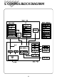
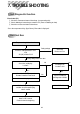
5. CONTROL BLOCK DIAGRAM
1
...
...
11
12
13
14
15
...
...
34