April.2012.
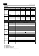
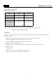
SPECIFICATIONS 1. Information Buyer No. Gross Vol. (ISO 15502) Storage Vol. (ISO 15502) Diemension X22D.. X22E.. X22F.. X22G..
SPECIFICATIONS 2.
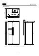
SPECIFICATIONS 3. Interior Parts ※ The real features are model dependent. 1. Door storage compartment ; for shot-term storage 2. Door storage compartment ; for storing frozen food 3. Freezer shelf ; for storing frozen food 4. Ice maker & storage case 5. Freezer case ; for storing dried or fish, meat for long periods of time. 6. Xpress can chiller ; for storing beverage ( quick cooling compartment ) 7. Refrigerator shelf ; for storing common foods 8. Egg case 9. Water tank ; for storing cold water 10.
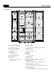
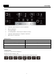
FUNCTIONS 1. Display a e b f c d a Temperature adjustment button for freezer compratment. b Dispenser light button. c Lock & Unlock button. d Ice selction(Cubed Ice , Crushed Ice) & Ice Maker Lock button. e Temperature adjustment button for refrigerator compratment. f Water dispenser selction button. 2. Display Control FCP Control Temp. Display (Set Temp.
FUNCTIONS 4. REF.SET button 1) Temperature control of refrigerator compartment 2) Initial power plug in : Medium ( 4C ) - Every time you press the REF.SET button, the setting temperature changes below order. 5. WATER/ICE select - Mineral Water Model Only 1) When push the WATER button, water dispensing available. 2) When push the ICE button, cubed ice dispensing available. 3) The initial mode is WATER. - Crusher + Mineral Water Model Only 1) When push the WATER button, water dispensing available.
FUNCTIONS ( Temperature Control ) 1. Freezer Compartment Control 1) Adjust by the pushing the FRZ.SET button. 2) Compressor & Freezer Fan controlled by each mode ON/OFF point. 3) Freezer Compartment ON/OFF Difference : 4C - MEDIUM OFF point : -19.
FUNCTIONS ( Temperature Control ) 2. Refrigerator Compartment Control 1) Adjust by the pushing the REF.SET button. 2) Refrigerator Damper controlled by each mode ON/OFF point. 3) Refrigerator Compartment ON/OFF Difference : 0.5C - MEDIUM OFF point : 6.0C 4) Weak Cooling Prevention Function - This funtion is free of Freezer sensor. - When refrigerator compartment reaches the OFF point, compressor is controlled by freezer sensor. - Weak cooling temperautre is + 7C in each dial sensor OFF temperature.
FUNCTIONS ( Fan Control ) 3. Fan voltage per control mode Exerted fan motor voltage Mode F-Fan C-Fan Normal mode 10 V 13 V Super Freezer mode 13 V 13 V Load mode / 4 hours after defrosting / RT >= 38C 13 V 13 V 1) Normal control : Slow operation mode with relatively low noise level. 2) Load mode : Operation mode which need to be operated by temperature rise at inner side of refrigerator according to operating condition. 4.
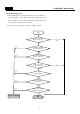
FUNCTIONS ( Defrost Mode ) 1. When Defrost Mode start? 1) When total Compressor runnig time becomes at 10,12,14..40hours. - Door opening time is over 2 minutes ( Each Freezer / Refrigerator door ) - Any error happens. ( R1, F1, D1, F3, RT-Sensor, C1, Door switch etc. ) - The compressor runing time is over 12 hours. 2) Total compressor running time ( on time + off time ) is 70hours.
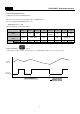
FUNCTIONS ( Defrost Mode ) 2. Normal Defrost Mode HEATER DEFROTING PAUSE FAN DELAY 1) HEATER DEFROSTING - Defrost heater is switch on until Defrost Sensor temperature reaches 13C. - Heater operation time ; 30 seconds - Heater is ON free of Defrost Sensor. ; 30 minutes - When Defrost Sensor is malfunction. ( D1 error ) ; 60 minutes - Heater maximum operation time. ( F3 error) 2) PAUSE - After Defrost Heater switch OFF, Compressor dosen't run within 10 minutes.
Error Display 1. How to enter this check mode 1) Push the LOCK button. 2) Push the WATER button 5 times while pressing the FRZ.SET button. 2. The Front LED displays the current error code ( if happens ). ; Every time you press the Freezer Set button, the following value display. 1) The appliance running time. ( From the plug in. ) 2) Freezer sensor temperature. 3) Defrost sensor temperature. 4) Refrigerator sensor temperature. 5) Room temperature. 6) P Factor display. 3.
FUNCTIONS ( Error Display ) 5. Troubleshooting when error happens ( If the relative parts is normal, Error code display will be reset. ) 1) F1 error - Cause : Freezer sensor disconnection or short. - Check point : Measure the resistance of freezer sensor in the Main PCB. If sensor is disconnected or short, change that in the freezer compartment. - Error code display Freezer sensor is short. Freezer sensor is disconneted. 2) R1 error - Cause : Refrigerator sensor disconnection or short.
FUNCTIONS ( Error Display ) 7) Et error - Cause : Level switch abnormal. ( No pulse is sensed for some time. ) - Control : By time. ( Supply mode is skipped. ) 8) Eg error - Cause : When Ice sensor temperature ( 5 minutes after water supply ) doesn't go up. - Check point : Ice sensor or water supply line. 9) EA error - Cause : When sensing ice drop 3 times in level sensor switch error. - Control : Stop ice maker - After 1 time rotation EA error code disappear if level swtich is normal.
FUNCTIONS ( Ice Maker ) 1. Ice making flow Start Making the Ice - water freezing water supply stand by Ice separating - Ice tray rotation to separate ice cubes Water supply - water supply to ice tray Water supply check - check if water supply complete or not End 1) Press Test switch ( which is under the ice tray ) for more than 1 second and then test starts. - Test mode starts from ice separating mode. - In case test switch is abnormal, test is done only 1 time.
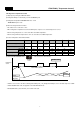
FUNCTIONS ( Ice Maker ) 2. Ice making mode Start NO Ice sensor is below -9.5C 70 minutes pass YES Ice sensor is over -12.5C NO YES NO 15 minutes pass NO YES YES Ice separating 1) If Ice sensor temperature is below -12.5C after 70minutes, ice making completes. 2) If Ice sensor temperature keep below -9.5C for 15 minutes ice making complete, although the sensor is not below -12.5C 3) After 4.8hours ice making complete, when ice sensor is abnormal, 3.
FUNCTIONS 4. Weak Cooling Trouble Shooting ; Adjust refrigerator sensor OFF point - Normal sensor resistance. (31.4kohm) - Cut the J18 and increase sensor resistance. (33.4kohm) - Cut the J18, J19 and increase resistance. (35.4kohm) Weak Cooling happens Option Normal 1.5C down 3.0C down J1 - Cut Cut J2 - - Cut 5 Magic cool zone ( *not 5. not all models ) Step Vegetable mode Fish mode Meat mode Fresh mode Damper Open 8C 4.5C 3C - Damper Close 7C 3.
FUNCTIONS 6. Pull Down Mode ( Test Mode ) 1) How to start - Push the LOCK button. - Push the ICE button 5 times while keep pressing the REF.SET & FRZ.SET button. 2) How to control : Compressor, Freezer Fan, Refrigerator Fan and Compressor Cooling Fan is ON for 30 hours. 3) Display : Co display in Error Mode 4) Termination : After 30 hours or power reset. 7. System Off function 1) Purpose: Stop refrigerator operating without unplugging especially on holidays. 2) How to start : Pressing FRZ.SET and REF.
FUNCTIONS KEYS - All the modes active in LOCK ( Push the LOCK button ) Mode How to enter A/S Forced Defrosting REF.SET button 5 times while keep pressing FRZ.SET button. Pull Down ICE button 5 times while keep pressing REF.SET & FRZ.SET button. Error Display WATER button 5 times while keep pressing FRZ.SET button.
WIRING DIAGRAM ( Inverter Compressor ) *Option Part(Crusher Function Model Only) 19
WIRING DIAGRAM ( Non Inverter Compressor ) Crusher Model Only 20
How to Disassemble / Assemble for each part 1.
How to Disassemble / Assemble for each part 2.
How to Disassemble / Assemble for each part 3.
How to Disassemble / Assemble for each part 4.
How to Disassemble / Assemble for each part 5.
How to Disassemble / Assemble for each part Evaporator in detail 26
How to Disassemble / Assemble for each part 6.
How to Disassemble / Assemble for each part 7.
How to Disassemble / Assemble for each part 8.
HOW TO Disassemble / Assemble for each part 9. Pump (Dispenser / Ice Maker) 1) Disassembling Procedure Procedure No No 1 Procedure 5 Pull out the water tank Unscrew 2 points with (+) driver 2 6 After Turning on water icon lamp , Press Pull both locker and Separate the cover button to drain water in the tube. on the left with thin driver.
TROUBLE SHOOTING 1.
TROUBLE SHOOTING 2.
TROUBLE SHOOTING 3.
TROUBLE SHOOTING 4. Disconnection / Breaking of Interior Lights Wire 4-1. Freezer Door Start Freezer light filament is disconnected or breaking? Yes Change the light bulb No No Connection of Freezer door switch Repair Door Switch Yes Check the Door Switch connection and light socket 4-2.
TROUBLE SHOOTING 6.
TROUBLE SHOOTING 5.
TROUBLE SHOOTING 7. Cold of Vegetable Case Start Yes Temperature setting Change to 'MIDDLE' mdoe No No Check Valve Repair or change the new Yes Any Refrigerator sensor Error? No No Sensor is ok? Repair or change the new Yes Check sensor connection (Check the connector to Main PCB) Yes Remark - Compressor sound is somewhat normal because it works like a heart to circulate the refrigerant in the pipes.
TROUBLE SHOOTING 8. Operation Noise of Refrigerator 8-1. Refrigerant Flow Sound Start Water flowing or hiss sounds? Yes Attach an absorber gum on the capillary tube Yes Apply a gum on the accumulator Yes Fasten the evaporator tightly not to touch liner surfaces.
TROUBLE SHOOTING 8-3. Pipe Noise Start Pipes are touching in the machine (compressor) compartment? Yes Separate the touching pipes, if any.. No Yes Tray drip makes noise by condenser shaking? Apply cushion matterial between compressor base and tray drip.
TROUBLE SHOOTING 9. Door opening alarm continues after closing Start No Check if interior light is ON Door switch pushing well? Attach a thin pad on the door liner or change the door assmbly.
TROUBLE SHOOTING 10.
TROUBLE SHOOTING 11. Dispenser (Water Supply ) Water-Leakage Points - Freshefood Compartment 1. Water tank Guide Front Image Back Image 2.
COOLING CYCLE HEAVY REPAIR 1. Summary of Heavy Repair Process Remove refrigerant Residuals Contents Tools Cut charging pipe ends (Comp. & Dryer) and discharge refrigerant from drier and compressor. Nipper, side cutters Parts replacement and welding Confirm refrigerant (R-134a or R-600a) and oil for compressor and drier. Confirm N2 sealing and packing conditions before use. Use good one for welding and assembly. Weld under nitrogen gas atmosphere. Repair in a clean and dry place.
COOLING CYCLE HEAVY REPAIR 2. Precautions During Heavy Repair Items Use of tools. Precautions - Use special parts and tools for R-134a or R-600a. Removal of retained refrigerant. 1) Remove retained refrigerant more than 5 minutes after turning off a refrigerator. (If not, oil will leak inside.) 2) Remove retained refrigerant by cutting first high pressure side (drier part) with a nipper and then cut low pressure side. (If the order is not observed, oil leak will happen.
COOLING CYCLE HEAVY REPAIR 3. Practical Work for Heavy Repair Items 1. Removal of residual refrigerant. Precautions 1) Remove residual refrigerant more than 5 minutes later after turning off the refrigerator. ( If not, compressor oil may leak inside.) 2) Remove retained refrigerant slowly by cutting first high pressure side (drier part) with a nipper and then cut low pressure side. Suction Low pressure Evaporato Hot Compresso Drye Process Discharge tube Condense ③ 2. Nitrogen blowing welding.
COOLING CYCLE HEAVY REPAIR Items 3.Vacuum degassing Precautions * Pipe Connection Connect a red hose to the high pressure side and a blue hose to the low pressure side. * Vacuum Sequence Open 1,2 valves and evacuate for 40 minutes. Close valve 1. Evaporato Compresso Hot Condense Drye Low Pressur High Pressur ① Vaccu m Blu ② Yello Re KEYPOINTING 1) If power is applied during vacuum degassing, vacuum degassing shall be more effective. 2) Operate compressor while charging refrigerant.
COOLING CYCLE HEAVY REPAIR Item 4.Refrigerant charging Precautions 4) Refrigerant Charging Charge refrigerant while operating a compressor as shown above. 5) Pinch a charging pipe with a pinch-off plier after completion of charging. 6) Braze the end of a pinched charging pipe with copper brazer and take a gas leakage test on the welded parts. Hot 5. Gas-leakage test * Take a leakage test on the welded or suspicious area with an electronic leakage tester. 6.
COOLING CYCLE HEAVY REPAIR Brzing Reference Drawings 48
Water System for Mineral Water Models 49
Cabinet Parts No Part Code Part Name Description Q'ty D/E * F / G* 1 - 1 1 2 3012933100 HINGE *T *R PO T3.0+PAINT 1 1 3 3012933000 HINGE *T *L PO T3.0+PAINT 1 1 ASSY CAB URT - 4 3001436800 COVER HI *T *R AS FRX-621B 1 1 4-1 3018125601 SWITCH H/BAR DR AS SP101B-2D1(G) GRAY 1 1 5 3001436700 COVER HI *T *L AS FRX-621B 1 1 3018125601 SWITCH H/BAR DR AS SP101B-2D1(G) GRAY 1 1 1 x x 1 1 1 1 1 5-1 7 30143KV070 22D..(None Inverter Comp.) 30143KV090 22D..
Compressor Room No Part Code 18 3010359600 19 OPTION 20 21 Part Name Description BASE COMP AS - 1 CORD POWER AS country dependent 1 3956183H4B MK183H-L2UB(220V/60HZ) 3956183D2B MK183D-L2UB(110~127V) 3956183Q5B 3956112250 COMPRESSOR MK183Q-L2UB(220~240V/50Hz) DG125E11RAW5(220~240V/50Hz) 3956114M80 LQ140NAEM(220~240V/50Hz) 3959115280 EU4A5Q-L2X, Inverter Comp.
Freezer Compartment No 33 33-1 33-2 Part Code 3017068900 3017068910 3014809500 3012824210 3012824220 Part Name EVA AS SENSOR D AS HEATER SHEATH AS Description 220-240V, 280W 110-127V, 250W PBN-43 220-240V, 280W 110-127V, 250W 1 1 1 35 3018928600 LOUVER F A AS 35-1 3015920700 MOTOR F FAN AS 1 35-2 3011836400 FAN F 1 36 3018928900 LOUVER F B AS FRY-621B 1 37 3001434700 COVER F RETURN HIPS 1 38 3012517800 GUIDE G MOTR BRKT*L ABS 1 39 3012517900 GUIDE G MOTR BRKT*R ABS 1 3010
Refrigerator Compartment PART-CODE D/F E/G 61 3016767100 DAMPER AS DU24-013 1 1 62a 3001436900 COVER DAMPER AS FRX-621B 1 1 62b 3015517000 WINDOW COVR DAMP GPPS 1 1 63 30143HJ220 PCB REF LED AS 9-LED FR-4 230X20-1.6T 1 1 64 3015517100 WINDOW R LED *T ABS 1 1 65 3017851300 SHELF R AS FRX-621B 1 1 66 3017858300 SHELF W/TANK TOTAL AS FPX-602 1 1 3012544900 GUIDE W/TANK CASE FPX-602,SILICON 1 1 66-1 PART NAME SPEC.
Freezer Door No Part Code 81 3019057900 POCKET F*M 3019058100 POCKET F*U 82 30100A4J00 30100A4J10 30100A4J20 83 ASSY F DR 2 GPPS 2 2 1 x x 1 1 1 1 1 FRX-601D 1 1 ABS 1 1 1 1 FRX-601D, TITANIUM VCM FRX-601D, WHITE VCM 30100A5J00 FRX-602D, TITANIUM ELLIO ASSY F DR 3012318860 3010574300 3010574310 BOX DISPNS I/SHUT AS 3001436601 COVER I/FLAP AS 83-2-2 3010573300 BOX DISPNS I/SHUT 3015403000 3015403120 FRX-602D, TITANIUM VCM FRX-602D, WHITE VCM FRX-602D, SUS430 GASKET
Refrigerator Door ( Middium Handle ) No 90 Part Code Part Name Description 30100A4K00 FRX-621B, TITANIUM ELLIO 30100A4K10 FRX-621B, TITANIUM VCM 30100A4K20 FRX-621B, WHITE VCM 30100A4K40 30100A4L00 ASSY R DR Q'ty D/E F/G 1 x x 1 FRX-621B, SUS430 FRX-601F, TITANIUM ELLIO 30100A4L10 FRX-601F, TITANIUM VCM 30100A4L20 FRX-601F, WHITE VCM 30100A4L40 FRX-601F, SUS430 90-1 3012318960 GASKET R DR AS PVC+MAGNET 1 1 91 3019058400 POCKET R*T GPPS 1 1 92 3019058800 POCKET MULTI
Refrigerator Door ( Long Handle ) No 90 Part Code Part Name Description 30100A5K00 FRX-622B, TITANIUM ELLIO 30100A5K10 FRX-622B, TITANIUM VCM 30100A5K20 FRX-622B, WHITE VCM 30100A5K40 30100A5L00 ASSY R DR Q'ty D/E F/G 1 X X 1 FRX-622B, SUS430 FRX-602F, TITANIUM ELLIO 30100A5L10 FRX-602F, TITANIUM VCM 30100A5L20 FRX-602F, WHITE VCM 30100A5L40 FRX-602F, SUS430 90-1 3012318960 GASKET R DR AS PVC+MAGNET 1 1 91 3019058400 POCKET R*T GPPS 1 1 92 3019058800 POCKET MULTI AS