S/M No. : Service Manual Drum Washing Machine Model: DWD-UD123X ✔ Caution : In this Manual, some parts can be changed for improving, their performance without notice in the parts list. So, if you need the latest parts information, please refer to PPL(Parts Price List) in Service Information Center (http://svc.dwe.co.kr). Mar.
DRUM WASHING MACHINE SERVICE MANUAL 1. What is Drum?...............................................................................1 2. Washer Specification.....................................................................4 3. Operating Mechanism Diagram.....................................................6 4. Each Part of Drum Washing Machine ...........................................8 5. Parts List By ASS'Y .....................................................................10 6.
1. WHAT IS DRUM Washing Machine? 1. Drum Washing Machine Water consumption is reduced by using the power of the laundry falling (free-fall) created when rotating the drum. With temperature control system, this drum washing machine saves energy and improves washing performance at the same time. 2. Key Features ◆ Waist Care Designed by the waist, and the most comfortable angle eject into the laundry is convenient and easy to manipulate. ◆ The World's First Shoes Course Enable to wash shoes.
3.
4. Major Functions 1 Washing When rotating drum after putting in the laundry and detergent into the drum, the laundry are rotated by protrusions (lifters) attached inside the drum. Washing is carried out with bending and impact actions generated by falling of the laundry to the bottom part of drum. 2 Rinsing Rinsing cleanly washes out detergent and dirt removed from the laundry after washing cycle. 3 Spin-drying Weak, standard and strong spin cycle can be selected according to types of fabrics to be washed.
2. Washer Specification 1.
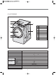
2 U127'S SERIES 6 4 8 5 7 3 1 2 DIMENSION(WxDxH) WASH 91 WASHING CONSUMPTION CABINET F 2 FRAME DOOR O 3 PROTECT GLASS 4 PANEL F 5 CASE DETERGENT 6 PLATE TOP 7 CABINET 8 BUTTON DIAL / DRY 51 31 POWER SOURCE CAPACITY 1 82 kg WATER CONSUMPTION CONSUMPTION PARTS NAME 630mm(W) x 792mm(D) x 991mm(H) MACHINE WEIGHT POWER NO 230V/50Hz, 110V/60Hz, 127V/60Hz WASHING 200W (Heating ) ~ 2000W DRY 1200W ~ 2100W WASHING 12 kg SPIN 12 kg DRY 7 kg WASHING TYPE DRUM TYPE DRY
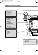
3. Operating Mechanism Diagram 4. WATER SUPPLY PART • Cold Water: 3 holes Cold water, pre-washing • Hot Water: 1 hole • Water supply box, hose Water Supply 6. DRY PARTS • HEATER DRY : OPTION • BLOWER FAN • FAN MOTOR : BLDC • THERMISTOR • THERMOSTAT : FUSE, BI-METAL • CONDENSING SYSTEM • DRY FAN DRIVE → GENERATION OF HEATER’S HEAT → TEMP. SENSOR → 110°C Off 100°C On : OPTION Detergent Container Thermister Door Door Switch 5.
1. CONTROL PART • Main PCB • Front PCB • Harness • Noise filter • Power Cord: 15A Electricity Input Noise Filter Program 2. DRIVING PART • BLDC motor • Drum • Bearing • Spider/ shaft • Tub • Weight balancer BLD C Motor Drum 3. HEATING PART • Water Heater: 1000W ~ 2000W • Washing temperature sensor Thermister 8.
4. Parts list by ass’y 1.
No Part Name Part Code Description Qt'y P1 BUTTON LIQUID 3616641600 ABS 1 P2 BUTTON RES 3616641700 ABS 1 P3 BUTTON SELECT DETERGENT 3616641800 ABS 1 P4 BUTTON ADD 3616641900 ABS 1 P5 BUTTON FUNCTION 3616643200 ABS 1 P6 SPRING BUTTON 3615116300 SUS, ID=9.5,d=0.
1.
No Part Name Part Code Description Qt'y P1 WINDOW COURSE R 3615508700 투명 ABS 1 P2 WINDOW COURSE L 3615508800 투명 ABS 1 P3 BUTTON POWER 3616643100 ABS 1 P4 DECORATOR BUTTON POWER 3611693300 ABS, 증착 1 P5 BUTTON START 3616643000 ABS 1 P6 DECORATOR BUTTON START 3611693200 ABS, 증착 1 P7 SPRING BUTTON 3615116400 SUS, ID=15,d=0.
2.
No Part Code Part Name Description B01 3610528200 BOX INLET PP 1 B02 3613274100 HOSE INLET EPDM 1 B03 3618110600 NOZZLE TOP PP 1 B04 3618110700 NOZZLE UNDER PP 1 B05 36189L7000 UNIT PUMP AS DWD-U120R 220-240V 50/60HZ 2 - 3612799200 HARNESS FEED DRUMUP-2ND, AUTO-FEED SUB-HARNESS 1 B06 3615304800 SUPPORTER BOX SBHG 1.2T 1 B07 3610610500 BRACKET SENSOR ABS 4 B08 3614825900 SENSOR LIQUID A TAB#250+PIPE(59.5) 1 B09 3614826400 SENSOR LIQUID B TAB#250+PIPE(64.
3.
No Part Code Part Name Description C01 3610813000 CABINET F SECD 0.8T, DWD-T120R 1 C02 3614539800 PLATE HINGE SUPPORT SPG 0.
4.
No Part Code Part Name Description D01 3618103110 NOZZLE AIR PP, DWD-100DR 1 D02 3612209300 FRAME TOP R DWD-T110R, GI 1.6T 1 D03 3612209400 FRAME TOP L DWD-T110R, GI 1.6T 1 D04 3610812900 CABINET SGCC 0.8T, DWD-T120R 1 D05 3611425540 COVER BACK AS COVER BACK + PAD CABINET 1 D06 3612209500 FRAME UPPER DWD-T110R, SBHG 1.2T 1 D07 3612204201 FRAME LOWER SGCC 1.
5.
No Part Name Part Code Description Qt'y Remarks E01 BASE U 3610393200 PP, DWD-T120R 1 E02 SUPPORTER LEG 3615303600 PO+도금, 3.0T 4 E03 FIXTURE LEG 3612006400 ABS, DWD-100DR 4 E04 SPECIAL BOLT 3616029000 10 X 1.25, 51MM 4 E05 FOOT 3612100600 BUTYL, DWD-100DR 4 E06 REACTOR 52G043J002 DWD-100DR, 4A 1 E07 DAMPER FRICTION 361A700150 110N AKS ST=170-260 DL=197.5 LOW NOISE 2 다른 끝단은 TUB AS에 체결 E08 DAMPER FRICTION 361A700110 70N AKS ST=170-260 DL=197.
6.
No Part Name Part Code Description Qt'y F01 BALANCER WEIGHT 3616109000 DWD-T120R 1 F02 GASKET DRY 3612323900 EPDM 1 F03 NOZZLE SHOWER 3618104000 PP, DWD-100DR 1 F04 DAMPER PIN 361A700200 AKS D=14.5 4 F05 DAMPER FRICTION 361A700110 AKS, 70N 2 F06 TUB FRONT 3618829800 FRPP, DWD-T120R 1 F07 DRUM FRONT 3617003101 SUS, 0.5T 1 F08 LIFTER WASH 361A400600 PP NANO-SILVER 3 F09 DRUM CENTER 3617003010 SUS, 0.6T 1 F10 DRUM REAR 3617003210 SUS, 0.
7.
No Part Name Part Code Description Qt'y G01 UNIT FAN MOTOR 36189L3Z20 ISM-7780 6DWWA 24V. 1 G02 COVER DUCT 3611428700 ALDC 1 G03 DUCT B UPPER 361A202100 ALCOST 0.5T 1 G04 CLAMP CORD 3611203330 DABE-2, A=9, B=5,3, L=105 3 G05 FAN AS 3611885900 DI33 FAN 1 G06 SCREW TAPPING 7122400811 T2S TRS 4x8 1 G07 SPECIAL SCREW AS 3616030100 TAPTITE P, TRS 4*16, WASHER 1 G08 FUSE TEMPERATURE 361A800120 128ûC(G4A0115C) 15A 250V 1 G09 FRAME HEATER FRANGE 3612209700 SBHG 1.
8.
9.
5. Control Part Function Specification 1. Function Specification 1) Sequence chart Division Senising P Water Supply r Pre. Wash e. W a Drain s Balancing Spin h Mid. Spin Senising Water Supply W a s h i n g R i n s e S p i n Washing 1 (Heating) Washing 2 Drain Balancing Spin Mid. Spin Water Supply Washing 1 Drain Balancing Spin Mid. Spin Water Supply WASHING 2 Drain Balancing Spin MID. SPIN Water Supply WASHING 3 Drain Balancing Spin Main Spin Normal Heavy stain Liquid DET. Power DET.
Division W a s h i n g Soal Water Supply Washing 1 (Heating) Washing 2 R i n s e S p i n D r y Drain Balancing Spin Mid. Spin Water Supply Washing 1 Drain Balancing Spin Mid. Spin Water Supply Washing 2 Drain Balancing Spin Mid.
Division Crease care Steam water supply Steam washing D r y Steam washing W a s h i n g R i n s e S p i n Finishing water supply Finishing washing Soal Water Supply Washing1 (Heating) Washing2 Drain Balancing Spin Mid. Spin Water Supply Washing 1 Drain Balancing Spin Mid. Spin Water Supply Washing 2 Drain Balancing Spin Mid. Spin Water Supply Washing 3 Drain Balancing Spin Mid.
Division W a s h i n g R i n s e S p i n Soal Water Supply Washing1 Drain Balancing Spin Mid. Spin Water Supply Washing 1 Drain Balancing Spin Mid. Spin Water Supply Washing 2 Drain Balancing Spin Main Spin Time rag Small stocking Small lingerie Small ■ ■ ■ ■ ■ ■ ■ ■ ■ ■ ■ ■ ■ ■ ■ ■ ■ ■ ■ ■ ■ ■ ■ ■ 30min 1min 5min 3min 1min 1min 1min 1min 1min 2min 1min 1min 1min 1min 2min 1min 1min 3min 2min 1min 60sec 10sec ■ ■ ■ ■ ■ ■ ■ ■ Crease care End End ■ ■ ■ Remain Time Display 19 13 18 NOTE 1.
2. Skill of each Sequence 2-1. Washing Sequence 1) Washing Sequence part Time Part LOAD SENSING Water Level Main O Pre O Soak O Course HEATING Washing Decision Level Decision Level Decision Level Decision Level X 8 or 10 min High X 30 min. 1 Prewash and Soak working previous main washing. 2 Decision Level’ decide Water Level and Time to Load Sensing in Normal, White, Eco-white course. 3 Soak consist of water supply and washing, after this, start main washing.
1 Washing Heater isn’t reworking after reach decision temperature. 2 The washing time is divided into the heating time and the main washing time that follows it. The heating time is gone immediately after the heating is finished or stopped until the heating is completed. 3 The heating time for the standard course with water temperature of 40 degrees includes seven minutes without any heating in the early stage.
4) Water supply 1 Depending on the course setting or load sensing, the water supply level is selected to be either low or extra low. 2 For powder DET injections, the main washing valve is opened and closed five times. 3 If liquid DET is selected, the liquid DET stirring motor operates 30 seconds for low levels and 20 for extra low levels. 4 When liquid DET is fully injected, the washing water supply including constant temperature control begins.
3) Sinse Sequence part Level height(mm) Water Temp. Rinse Time MOTOR On/OFF (sec) Mid. Spin Mid. Spin r.p.m rpm. Water supply rinse Normal Cold 3min 3min Medium 45 r.p.m 5/15 10/5 Whites Cold 3min 3min Small 45 r.p.m 5/15 10/5 Steam soak Cold 3min 3min Medium 45 r.p.m 5/15 10/5 Heavy stain Cold 3min 3min Medium 45 r.p.m 5/15 10/5 Baby care Cold 3min 3min Small 45 r.p.m 5/15 10/5 Sports shoes Cold 3min 3min Small 45 r.p.
2-3 Spin Sequence 1) Water discharge 1 It is done according to functional organization 3-5, water discharge sequence. 2) Balanced spin 1 Depending on the amount of water, 3 steps of unbalance checks are done. If the criteria is satisfied, then it advances to the next stage, spin R. 2 Spin B refers to the unbalance detection area at 350 rpm. If the amount of unbalance exceeds the reference value, then it turns back to the textile attachment region. 3 Press the pause button in the middle of spin B.
2-4 Termination 1) Textile pulling 1 After the spin is completed, the laundry is taken off from the drum wall to prevent wrinkles. It lasts for 30 seconds. 2 The motor operation depends on the type of textile pulling. 3 No textile pulling is done for soft textile, sports shoes, hand cloths, stockings and lingerie. 2) Termination 1 The buzzer sound will be heard for 10 seconds after completing textile pulling. Also the power is off. 2 If a drying cycle is added, then it will proceed to drying.
4) Motor conduction time for a drying cycle Textile pulling Drying Cooling Wrinkle free Cycle time (min) Heater off/on Low temperature 10/5 15/5 10/10 10/50 110 70/60 Low temperature (sports shoes) 10/5 2/30 2/30 X 36 70/60 Ironing 10/5 15/5 10/10 10/50 60 105/95 Standard 10/5 15/5 10/10 10/50 150 105/95 Strong 10/5 15/5 10/10 10/50 200 105/95 1 You can select one of 1 hr/ 90 minutes/2 hours.
2) Steam heating 1 The heater operates until the target water temperature is reached. 2 Steam heating temperature setting Course Temperature setting Time setting Power saving 70ûC 15 min Standard 75ûC 15 min Strong 90ûC 20 min 3 When the target temperature is reached, the time set for steam heating is reduced. 3) Steam washing 1 The water temperature is maintained and the steam effect is maximized in this operation.
3. Main Function of PCB Program 3-1. LOAD SENSING 1) Deciding the water level ① Normal, White, Eco-White Course will be followed by this process. ② Check the water level with dry laundry at the starting wash. ③ Check the water level by using motor output data during 20 sec, 65rpm. 2) Deciding Spin Starting Step. ① Check after finishing washing step with wet laundry. ② Checking by using motor output data during 20 sec, 65 rpm. ③ The Decided data is different depending on loading condition. 3-2.
3-3. DOOR S/W 1) The working principle of Door S/W ① Door Locking Bimetal on (3 sec) --> solenoid (supply 20msec pulse 2 times) ② Door Unlocking Bimetal off --> solenoid(supply 20msec pulse, until lock) ③ After door locking all parts can work nomally. ④ After pressing power button, if the temperature of wash thermistor is over 55℃ or the water level is over the safety level, the door will be locked. ⑤ The door will be unlocked immediately after all processes are finished.
Start/Hold Door unlock button, 2sec ON Water level is less than safety level? NO Drainage YES Temperature is less than 50℃? NO YES DISPLAY ‘LOCK’ OFF Door Open 40 Cold water supply
5. TEST MODE 5-1. Testing Mode PCB and other electronic parts will be tested without water supply whether they are normal or not. 1) Process press power button --> press "SPIN" button 3 times with pressing "WASH" button --> 'L d' will be shown on LED --> Whenever pressing "TEMP" button 1 time, below process will be occurred. MICOM Ver.
6-1. Error Display 6-1. IE (Input Error) - Error in water supply 1) Conditions of Occurrence ① In case the designated water level is not reached in 5 minutes during water supply or re-supply 2) All LEDs are turned off and 'IE' blinks in18:88 display. 3) Error buzzer alarm is sounded for 10 seconds per every 10 minutes. 4) Error display is cleared when turning off/ on power. 6-2.
6-4. LE (Lock Error) - Door opening error 1) Conditions of Occurrence ① When intending to begin cycle by pressing start/ temporary stop button while door is opened 2) All LEDs are turned off and 'LE' blinks in 18:88 display. 3) Error buzzer alarm is sounded for 10 seconds per every 10 minutes. 4) Error display is cleared when turning off/ on power. 6-5.
6-7. E4 - Water leakage during washing 1) Conditions of Occurrence ① In case water level falls below re-supply even after 15 times of re-supply prior to finishing of water heating 2) All LEDs are turned off and 'E4' blinks in 18:88 display. 3) Error buzzer alarm is sounded for 10 seconds per every 10 minutes. 4) Error display is cleared when turning off/ on power. 6-8.
6-9. Motor-related Error 1) E5 (DC-Link High Voltage) Error ① In case DC-link voltage to IPM increases to 450V or higher ② Motor operation is stopped and 'E5' is shown in display window. ③ Error buzzer alarm is sounded for 10 seconds per every 10 minutes. ④ Error display is cleared when turning off/ on power. 2) E6 (EMG) Error ① In case current detected with EMG port is of 20A or higher ② Motor operation is stopped and 'E6' is shown in display window.
3) H5 Error - Water temperature error in wool/ delicate course ① In case water temperature in wool/ delicate course is 45℃ or higher ② Error buzzer alarm is sounded for 10 seconds per every 10 minutes. ③ Error display is cleared when turning off/ on power.
7. ELECTRONIC FIELD PARTS LIST AND SPECIFICATION 1. PCB PIN Relay (S/W) Relay (Heater S/W) 세탁전용일 경우 삭제됨.
2.
Water supply not carried out (IE) • Suspension of water supply • Tap frozen • Tap closed • Hot & cold water hose switched for connection • Low water pressure (0.
Symptoms of Inspection Spot Breakdown Inspection Method Inspection Result Problem Identified 1) Suspension of water supply 2) Water tap locked 3) Cold-hot water hose incorrectly - Cold/ hot water hose switched -Defect in cold/ hot water connected -Large amount of rust, sand and hose assembly 4) If no defect is found, dismantle water dust, etc. -Defect in cleaning of water supply hose and check water supply supply filter (blocked) valve filter.
3. Water Level Sensor 1) Spec. of Water Level Sensor (kHz) HEATER SAFETY 24.55 STEAM 24.736 O/F: Forced drainage is necessary as water level is high. When this level is reached, water supply must be stopped and drainage must be forcefully administered. RESET 25.2 LOW 23.2 RESET : MID 23.75 RINSE 23.18 ADD WATER OVERFLOW 22.96 22.6 Low: Small load of laundry, therefore considered to be water level of 'low' 1. Spin-drying begins 30sec after drainage level reset is reached.
4. POWER CORD 1) Specificafion Classification Rated Cord Thickness Color DEC 250V/15A 1.5sq Gray DEC 125V/13A 1.5sq DEC 250V/16A DEC 125V/15A Code Type Length Remarks 3611339340 LP-31 SJT 2.3m - Gray 3611340410 UL.SJT 2.3m - 1.5sq Gray 3611339930 EU-2P 2.3m - 2.0sq Gray 3611339810 BSMI 2.3m - 2) Assembly 4 embossed parts in cabinet -> To prevent loosening after assembly -> SS: 2 special screws -> LG: Forced indentation [Before] [After] .
5.
4) Diagnosis of Defect Symptoms Detailed Symptoms Cause Diagnosis of Defect Solution Ticking noise Tick' during initial operation and 'tick-tick' during temoprary suspension: 'DF' type only Normal noise Normal sound generated during solenoid operation when 'sliding CAM' is locked/ unlocked to close or open door. LE' Continuous occurrence of 'tick' noise and 'LE': 'DF' type only Connector loosened Visually checking connector connection status 1.
1.
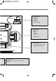
2) Dry Function Diagram T : Thermistor (CONTROL HEATER’S TEMPERATURE ) DRY DUCT HEATER T FAN MOTOR WATER SUPPLY CONDENSING DUCT DRUM DRAIN HOUSING While rotating DRUM, DRY HEATER applice heat to air and FAN blows it into DRUM evaporating water in the laundry. • Evaporated water is sucked into CONDENSING DUCT, and condensed in DUCT contacting WATER SUPPLY (condensed water is extracted through DRAIN HOUSING).
4) Dry Course COURSE LOW TEMP.
5) TROUBLE SHOOTING OF DRY SYSTEM ✦ HEATER DRY Function : heating the air during dry • FAILURE MODE : * "H7" - The air cannot be heated to 10°C during 2 min. • CHECKING METHOD : * Check the resistance of heater coil and replace with new one. ✦ Thermistor Function : sensing the air temperature. • FAILURE MODE : * The air cannot be heated even though water is supplied. * "H1" - shot or cut-off * "H3" - air temp.
✦ SWITCH THERMOSTAT(BIMETAL) function : control the duct temperature, if the temp reached over 150°C, all power supply will be cut. and if the temp go down 120°C the power will be ON. protecting overheating by cutting off heater power supply if the temperature rises over 150°C, and reoperating heater by connecting heater power supply if the temperature falls under 120°C.
6) LACK OF DRY PERFORMANCE • Situation : after drying, the clothes still get wet. cause) ☞The laurdry amount is more than the recommendation capacity 7.0kg. ☞Condensing cold water is not supplied. ☞Clogging Bellows Duct results in poor air circulation.
• Situation : PCB shows "H7". cause) ☛ Dry heater is cut-off. ☛ Fuse temp. is cut-off. repaire method) ☛ replace the Dry heater. ☛ replace the Fuse temp. checking point part name HEATER FUSE TEMPERATURE checking results repaire method dry Heater is short or cut-off. replace the dry Heater. SENSOR TEMP. Thermistor is short or cut-off. replace the Thermistor. FUSE TEMP. FUSE TEMPERATURE is cut-off. HEATER DRY THERMISTOR 61 replace the FUSE TEMPERATURE.
• situation : PCB shows "E3". ☞FAN MOTOR can not work. ☞Replace the Fan Motor.
Washing Heater Temp. Sensor Table TEMP ℃ -40 -39 -38 -37 -36 -35 -34 -33 -32 -31 -30 -29 -28 -27 -26 -25 -24 -23 -22 -21 -20 -19 -18 -17 -16 -15 -14 -13 -12 -11 -10 -9 -8 -7 -6 -5 -4 -3 -2 -1 MIN KΩ 282.914 266.642 251.432 237.208 223.900 211.440 199.683 188.669 178.347 168.668 159.588 150.999 142.937 135.366 128.253 121.566 115.230 109.271 103.665 98.387 93.416 88.603 84.072 79.806 75.788 72.000 68.408 65.021 61.825 58.810 55.963 53.214 50.620 48.171 45.857 43.670 41.594 39.630 37.773 36.016 R25 : 11.
R40 : 26.065KΩ ± 3% R100 : 3.3KΩ ± 11.1% B40/100 : 4025K ± 2% Day Heater Temp. Sensor Table T(℃) 0 1 2 3 4 5 6 7 8 9 10 11 12 13 14 15 16 17 18 19 20 21 22 23 24 25 26 27 28 29 30 31 32 33 34 35 36 37 38 39 40 41 42 43 44 45 46 47 48 49 50 51 52 53 54 55 Rmin 142.55 135.55 128.93 122.68 116.76 111.17 105.87 100.86 96.12 91.62 87.37 83.33 79.51 75.88 72.44 69.17 66.07 63.13 60.34 57.68 55.16 52.76 50.48 48.31 46.25 44.28 42.41 40.63 38.94 37.32 35.78 34.31 32.91 31.58 30.31 29.09 27.93 26.83 25.77 24.
7. HEATER 1) Spec of Heater of Washing Machine WASH MAKER IRCA IRCA IRCA IRCA RATED 220V 230V 130V 110V 2000W 2000W 1000W 1000W 3612802400 3612802410 3612802440 3612802430 CONSUMPTION POWER PART CODE DRYER MAKER IRCA IRCA IRCA IRCA RATED 220V 230V 120V 110V 2100W 2100W 1200W 1200W 3612800900 3612801400 3612802100 3612801300 CONSUMPTION POWER PART CODE Temp. Fuse of Washing Heater (184°C CUT OFF TYPE) : Located inside heater to prevent fire, etc.
2) Breakdown Diagnosis Breakdown Symptoms Solution PCB Error Mode Check for short Connect the cut-off part. "H6" Check for short: Normal if 23.3~25.7ohm between both terminals of washing heater Replace washing heater. "H6" Connector/ terminal loosening Check for loosening: Common for drum Insert terminal. "H6" Defect in washing heater temp. sensor Measuring resistance between both terminals of sensor: Replace temp. sensor. "H2" Overheating of Defect in washing washing water heater temp.
7.
3) Specification Classification 1. General 2. Performance 3. Structure Item BLDC : DD Motor Rated Voltage Vm = 310 [Vdc], Hall IC Voltage 5 [Vdc] Insulating Structure Type B, insulator method External Appearance Shaft connection and stator connection structure, Air-gap : 1mm No. of Poles 24 poles, Core: 36 slots, Layer: [30mm] Consumption Power 390[W]±10[%], during washing (picked value) RPM During Washing: 45RPM, During Spin-drying:1300RPM Output Characteristics Torque: 300Kgf.
8.
9. TROUBLE SHOOTING REGARDING DRAIN 1) Structure of Dran Parts by TUB HOSE DRAIN I HOUSING VALVE DRAIN MOTOR VALVE AIR AS 2) Checking Methods • Situation : * "OE" is shown on PCB. * Not finishing drain during 10 min. * The water level can not reach to RESET POINT during 10 min of drain. Checking Methods Replacing methods * Check the hose drain O condition; twisted or frozen. * replace HOSE DRAIN O * Check the hose drain O condition, blocked. * clean the inside of Filter. * DRAIN MOTOR is broken.
10. INSTALLATION GUIDE 1) Related Parts and Configuration FIGURES PARTS NAME REMARKS FIXTURE UP/DOWN AS SPECIAL FIXTURE UP SCREW UP FIXTURE DOWN SPECIAL SCREW DOWN FIXTURE UP AS (3612008200) : L= 109mm FIXTURE DOWN AS (3612008300) : L=143mm ① Remove Fixture UP/DOWN AS ② Adjust Leg UNIT SERVICE WRENCH LEG ADJUST AS FIXTURE LEG FOOT 2) INSTALLATION PROCESS 1Remove the FIXTURE UP/DOWN AS Removal Method Remarks ☞ Disassemble the FIXTURE UP/DOWN AS by turning CCW direction.
3Please install the DRUM WASHING MACHINE properly on even and hard floor as below. 4Adjust the level of washer using LEG ADJUST AS. Adjusting Method Remarks ☞ If turned CW, the LEG ADJUST AS moves the washer upward. ☞ If turned CCW, the LEG ADJUST AS moves the washer downward. 5After adjusting level, fix SPECIAL BOLT. Adjusting Method Remarks ✰ Please fix the SPECIAL BOLT by rotating it CCW in order to prevent washer vibration.
11.
DAEWOO ELECTRONICS CORP. 1-2, Jeo-dong 1(il)-ga, Jung-gu, Seoul, Korea C.P.O. BOX 8003 SEOUL, KOREA TELEX: DWELEC K28177-8 CABLE: “DAEWOOELEC” S/M NO. : PRINTED DATE: Mar.
ABOUT THIS MANUAL VISION CREATIVE, INC. 서울 종로구 통의동 6번지 이룸빌딩 4층 담 당 이영배 님 MODEL DWD-UD123X (S/M) 접 2010.03.02 총 76페이지 수 1차 2차 일 정 3차 4차 5차 제 판 규 격 인 한 쇄 MEMO 총 76p 10.03.02-전체 신규 76p 10.03.