S/M No. : OC9Q3T7S01 Service Manual Microwave Oven Model: KOC-9Q4T ✔ Caution : In this Manual, some parts can be changed for improving, their performance without notice in the parts list. So, if you need the latest parts information, please refer to PPL(Parts Price List) in Service Information Center (http://svc.dwe.co.kr). Mar.
. SPECIFICATIONS MODEL KOC-9Q3T7S POWER SUPPLY 230V~50Hz, SINGLE PHASE WITH EARTHING MICROWAVE 1400W POWER GRILL 1250W CONSUMPTION CONVECTION 1250W COMBINATION 2700W MICROWAVE ENERGY OUTPUT 900W (IEC 705) MICROWAVE FREQUENCY 2450MHz OUTSIDE DIMENSIONS (W X D X H) 513X382X311mm(20.2X15X12.2 in.) CAVITY DIMENSIONS (W X D X H) 354X341X231mm(13.9X13.4X9.1 in.) NET WEIGHT Approx. 16.6Kg (46.6 lbs.
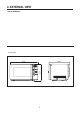
. EXTERNAL VIEW 1.
2. FEATURE DIAGRAM 2 3 4 5 6 7 8 1 9 13 12 11 10 11. DOOR HOOK Hook automatically locks and holds the door when the door shuts. If the door opens while the oven is operating, the oven will stop operating immediately. 12. DOOR SEAL Door seal prevents the microwave leakage from the oven cavity. 13. DOOR VIEWING SCREEN Food, inside of oven, can be observed through the door viewing screen. It is designed that the microwave cannot pass through the screen. 14.
2) KOC-9Q4T 1 2 4 5 3 6 7 2 Auto cook : Used to cook or reheat. q 8 9 0 1 Display : Cooking time, power level, program indicators and present time are displayed. MW ( ): When blinking, the oven is operating in MICROWAVE COOK mode. Grill ( ): When blinking, the oven is operating in GRILL mode. Combi ( ): When blinking, the oven is operating in COMBI mode. Convection ( ): When blinking, the oven is operating in CONVECTION mode. Defrost ( ): When blinking, the oven is operating in DEFROST mode.
8. TROUBLESHOOTING GUIDE Following the procedure below to check if the oven is defective or not. 1) Check grounding before trouble checking. 2) Be careful of the high voltage circuit. 3) Discharge the high voltage capacitor. 4) When checking the continuity of the switches, fuse or high voltage transformer, disconnect one load wire from these parts and check continuity with the AC plug removed. To do otherwise may result in a false reading or damage to your meter.
CONDITION CHECK RESULT CAUSE REMEDY Outlet has proper voltage fuse does not blow? Check continuity of magnetron No continuity Defective magnetron. Replace Check continuity of noise filter board No continuity Defective line filter board Replace Check continuity of power supply cord No continuity Open power supply cord Replace No continuity Defective touch control circuit Replace NOTE : All these switches must be replaced at the same time, please refer to (7.
TROUBLE 3) No microwave oscillation even though fan motor rotates.
(TROUBLE 4) Grill heater (upper heater) is not heated; food will not become hot. CONDITION Main heater is not heated. CHECK RESULT CAUSE REMEDY Check continuity of primary interlock switch No continuity Malfunction of primary Interlock switch Adjust or replace Check continuity of DOM switch No continuity Malfunction of DOM switch Adjust or replace Check continuity of heater No continuity Defective heater Check D.
(TROUBLE 6) The following visual conditions indicate a probable defective touch control Circuit or button P.C.B. assembly 1. Incomplete segments. 1) segment missing 2) partial segments missing 3) digit flickering other than normal fluorescent slight flickering 2. A distinct change in the brightness of one or more numbers exists in the display. 3. One or more digits in the display are not on when they should be. 4. Display does not count down or up with time cooking or clock operation. 5.
9. MEASUREMENT AND TEST 1. MEASUREMENT OF THE MICROWAVE POWER OUTPUT Microwave output power can be checked by indirectly measuring the temperature rise of a certain amount of water exposed to the microwave as directed below. PROCEDURE 1. A cylindrical container of borosilicate glass is used for the test. It has a maximum thickness of 3mm, an external diameter of approximately 190mm and a height of approximately 90mm. The mass of the container is determined. 2.
2. MICROWAVE RADIATION TEST WARNING 1. Make sure to check the microwave leakage before and after repair of adjustment. 2. Always start measuring of an unknown field to assure safety for operating personnel from microwave energy. 3. Do not place your hands into any suspected microwave radiation field unless the safe density level is known. 4. Care should be taken not to place the eyes in direct line with the source of microwave energy. 5.
3. COMPONENT TEST PROCEDURE • High voltage is present at the high voltage terminal of the high voltage transformer during any cooking cycle. • It is neither necessary nor advisable to attempt measurement of the high voltage. • Before touching any oven components or wiring, always unplug the oven from its power source and discharge the capacitor. 1. High voltage transformer 1) Remove connections from the transformer terminals and check continuity. 2) Normal readings should be as follows : Secondary winding .
10.
1. DOOR ASSEMBLY Refer to 6. Disassembly and assembly. 2. CONTROL PANEL ASSEMBLY Refer to 6. Disassembly and assembly. 3.
✔ Caution : In this Manual, some parts can be changed for improving, their performance without notice in the parts list. So, if you need the latest parts information, please refer to PPL(Parts Price List) in Service Information Center (http://svc.dwe.co.kr). REF. NO PART CODE PART NAME DESCRIPTION H01 3516119900 CAVITY AS KOC-9Q0T7S 1 H02 3511403800 COVER WAVE GUIDE MICA T0.35 1 H03 7113400810 SCREW TAPPING T1 BIN 4X8 STS430 MFZN 1 H04 3511414800 COVER LAMP PE 0.
✔ Caution : In this Manual, some parts can be changed for improving, their performance without notice in the parts list. So, if you need the latest parts information, please refer to PPL(Parts Price List) in Service Information Center (http://svc.dwe.co.kr). REF. NO PART CODE PART NAME DESCRIPTION H39 3512529400 GUIDE WIND AS KOC-9Q0T7S 1 H40 7122401211 SCREW TAPPING T2S TRS 4X12 MFZN 1 H41 35113A5QJ5 CORD POWER AS 3X1.5 80X80 120-RTML 1.
12. PRINTED CIRCUIT BOARD CIRCUIT CHECK PROCEDURE 1. Low voltage transformer check The low voltage transformer is located on the P.C.B. Measuring condition: Input voltage: 230V / Frequency: 50Hz 1 9 Terminal Voltage(load) Voltage(no load) 8 7 7-8-9 DC 13.5 V AC 37 V 3 NOTE 1. Secondary side voltage of the low voltage transformer changes in proportion to fluctuation of power source voltage. 2. The allowable tolerance of the secondary voltage is within ± 5% of nominal voltage. 2.
MP1 MP2 MEASUREPOINT 39
3. Case of no microwave oscillation 1) When touching M/W button, oven lamp turns on and Fan motor and turntable rotate, and cook indicator in display comes on. *Cause: RELAY 1 does not operate. B A RY1 (MAGNETRON) D8 R31 D10 R32 D11 RY2 (LAMP,TRAY,FAN) (CONV.FAN) 23 P12 Q11 22 P13 Q13 V2 R21 STATE POINT A POINT B RELAY 1 ON +5V DC GND RELAY 1 OFF GND 12V DC 2) When touching M/W button, oven lamp does not turn on and turntable motor does not rotate but cook indicator in display comes on.
4. Case of no heating of top heater main. When touching GRILL or COMBI or CONVECTION button, oven lamp turns on and fan motor and turntable rotate, and cook indicator in display comes on. *Cause: RELAY 3 does not operate. A R16 B 24 P11 RY3 (GRILL) Q8 D7 Q7 STATE POINT A POINT B RELAY 3 ON +5V DC GND RELAY 3 OFF GND 12V DC 5. Case of no heating of top heater sub.
6. Case of no stopping of the count down timer When the door is opened during operation, the count down timer does not stop. V1 A CN1 YW396-02V D6 1N4148 1 B Q6 A1266Y 28 V2 2 R9 4.7K R11 10K R10 47K C1 104Z V1 D.O.M SW - Check method POINT A B DOOR OPEN OPEN +5V DC DOOR CLOSED CLOSE GND STATE CHECK NO 1 METHOD Check the stage(ON,OFF) of the door open monitor switch by resistance measurement. 42 REMEDY Replace door open monitor switch.
13. P.C.B.
PCB ASS’Y PART LIST NO 1 2 3 4 5 6 7 8 9 10 11 12 13 14 15 16 17 18 19 20 21 22 23 24 25 26 27 28 29 30 31 32 33 34 35 36 37 38 39 40 41 42 43 44 45 LOCATION BZ1 CA1 C7 C4,C6 C1~3,C5,C8,C9 EC1 EC2 CN1 CN2 CN3 CN5 D1~D13 D14,D15 IC1 IC2 VL1 DP1 M298 RA1 R1~R8 R12,18,25,26,33 R9,16,20,32 R11,19,R22~24,R27~29 R10,30 R17 R21 R31 R14 R15 CR1 RY1,3 RY2,4 Q1~Q5 Q7,9,11,12,14 Q6 Q8.
DAEWOO ELECTRONICS CORP. 1-2, Jeo-dong 1(il)-ga, Jung-gu, Seoul, Korea C.P.O. BOX 8003 SEOUL, KOREA TELEX: DWELEC K28177-8 CABLE: “DAEWOOELEC” S/M NO. : PRINTED DATE: Mar.