S/M No. : R63D79S002 Service Manual Microwave Oven Model: KOR-63D79S KOR-63D70S KOR-63F79S KOR-63F70S ✔ Caution : In this Manual, some parts can be changed for improving, their performance without notice in the parts list. So, if you need the latest parts information,please refer to PPL(Parts Price List) in Service Information Center (http://svc.dwe.co.kr). DAEWOO ELECTRONICS CO., LTD.
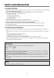
PRECAUTIONS TO BE OBSERVED BEFORE AND DURING SERVICING TO AVOID POSSIBLE EXPOSURE TO EXCESSIVE MICROWAVE ENERGY (a) Do not operate or allow the oven to be operated with the door open.
SAFETY AND PRECAUTIONS 1. FOR SAFE OPERATION Damage that allows the microwave energy (that cooks or heats the food) to escape will result in poor cooking and may cause serious bodily injury to the operator. IF ANY OF THE FOLLOWING CONDITIONS EXIST, OPERATOR MUST NOT USE THE APPLIANCE. (Only a trained service personnel should make repairs.) (1) A broken door hinge. (2) A broken door viewing screen. (3) A broken front panel, oven cavity. (4) A loosened door lock. (5) A broken door lock.
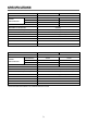
SPECIFICATIONS MODEL KOR-63D79S POWER SUPPLY POWER CONSUMPTION KOR-63D70S 230V~50Hz, SINGLE PHASE WITH GROUNDING MICROWAVE 1000W 1,200W 700W 800W GRILL COMBINATION MICROWAVE ENERGY OUTPUT MICROWAVE FREQUENCY 2450MHz OUTSIDE DIMENSIONS (W x H x D) 465 x 279 x 364 mm (18.3 x 11.0 x 14.4 in) CAVITY DIMENSIONS (W x H x D) 290 x 220 x 306 mm (11.4 x 8.7 x 12.0 in) NET WEIGHT APPROX. 13kg (28.7 Ibs.) TIMER 35 MIN.
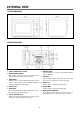
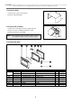
EXTERNAL VIEW 1. OUTER DIMENSION 2. FEATURE DIAGRAM 1. SAFETY INTERLOCK SYSTEM 7. ROLLER GUIDE This must always be used for cooking together with the glass cooking tray. 2. DOORVIEWING SCREEN Allos viewing of food. The screen is designed so that light can pass through, but not the microwave. 8. COUPLER This fits over the shaft in the center of the ovens cavity floor. This is to remain in the oven for all cooking. 3. DOOR HOOK When the door is closed, it will automatically lock shut.
INSTALLATION 1. Steady, flat location. This microwave oven should be set on a steady, flat surface. 2. Leave space behind and side. All air vents should be kept a clearance. If all vents are covered during operation, the oven may be overheated and, eventually, cause oven failure. 3. Away from radio, and TV sets Poor television reception and radio interference may result if the oven is located close to a TV, radio, antenna, or feeder and so on. 4.
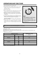
OPERATIONS AND FUNCTIONS 1. Connect the main lead to an electrical outlet. 2. After placing the food in a suitable container, open the oven door and put it on the glass tray. The glass tray must always be in place during cooking. 3. Close the door securely. 4. Choose cooking power level by setting V.P.C knob to the desired position. Refer to cookbook for recommended power levels. 5. Determine cooking time. Consult cookbook for recipe timing. Oven light turns on and cooling fan starts to operate.
DISASSEMBLY AND ASSEMBLY Cautions to be observed when trouble shooting. Unlike many other appliances, the microwave oven is high-voltage, high-current equipment. It is completely safe during normal operation. However, carelessness in servicing the oven can result in an electric shock or possible danger from a short circuit. You are asked to observe the following precautions carefully. 1. Always remove the power plug from the outlet before servicing. 2.
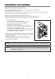
✔ Caution: In this Service Manual, some parts can be changed for improving, their performance without notice in the parts list. So, if you need the latest parts information, please refer to PPL(Parts Price List) in Service information Center(http://svc.dwe.co.kr) 1. To remove cabinet 1) Remove three screws on cabinet back. 2) Push the cabinet backward. 2. To remove door assembly 1) Remove two screws which secure the stopper hinge top. 2) Remove the door assembly from top plate of cavity.
(1) Remove the gasket door from door weld as. (2) Remove the door frame from door weld as. (3) Remove the stopper hinge top from door weld as. (4) Remove the spring and the hook. (5) Remove the barrier screen outer from door frame. (6) Reverse the above steps for reassembly. 4. Method to reduce the gap between the door seal and the oven front surface. (1) To reduce gap located on part ‘A’ Loosen a screws on stopper hinge top, and then push the door to contact the door seal to oven front surface.
✔ Caution: In this Service Manual, some parts can be changed for improving, their performance without notice in the parts list. So, if you need the latest parts information, please refer to PPL(Parts Price List) in Service information Center(http://svc.dwe.co.kr) 5. To remove control panel parts. REF NO.
6. To remove high voltage capacitor. 1) Remove a screw which secure the grounding ring terminal of the H.V. diode and the capacitor holder. 2) Remove the H.V. diode from the capacitor holder. 3) Reverse the above steps for reassembly. ◆ High voltage circuit wiring 7. To remove magnetron. 1) Remove a screw which secure the magnetron. 2) Remove the magnetron. 3) Reverse the above steps for reassembly.
NOTE : Never install the magnetron without the metallic gasket plate which is packed with each magnetron to prevent microwave leakage. Whenever repair work is carried out on magnetron, check the microwave leakage. It shall not exceed 4mW/cm2 for a fully assembled oven with door normally closed. 8. To remove wind guide assembly. 1) Remove a screw for earthing. 2) Remove the noise filter from the wind guide. 3) Remove a screw which secure the wind guide assembly. 4) Draw forward the wind guide assembly.
INTERLOCK MECHANISM AND ADJUSTMENT The door lock mechanism is a device which has been specially designed to completely eliminate microwave radiation when the door is opened during operation, and thus to perfectly prevent the danger resulting from the leakage of microwave. (1) Primary interlock switch When the door is closed, the hook locks the oven door. If the door is not closed properly, the oven will not operate. When the door is closed, the hook pushes the button of the microswitch.
TROUBLE SHOOTING GUIDE Following the procedure below to check if the oven is defective or not. 1. Check grounding before trouble checking. 2. Be careful of the high voltage circuit. 3. Discharge the high voltage capacitor. 4. When checking the continuity of the switches, fuse or high voltage transformer, disconnect one lead wire from these parts and check continuity with the AC plug removed. To do otherwise may result in a false reading or damage to your meter.
Does the fan motor work when you shut the door and turn the timer? YES Does the oven lamp light? Does the turntable turn? NO Replace or repair oven lamp, turntable motor. YES Normal reading should be approx. 0Ω If microwave do not oscillate, check continuity of filament of magnetron. NO Continuity Check continuity filament tap (3.3V) of high voltage. No Continuity Replace high Voltage transformer Continuity Poor continuity Check continuity filament tap (3.3V) of high voltage.
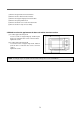
MEASUREMENT AND TEST 1. MEASUREMENT OF THE MICROWAVE POWER OUTPUT Microwave output power can be checked by indirectly measuring the temperature rise of a certain amount of water exposed to the microwave as directed below. PROCEDURE 1. Microwave power output measurement is made with the microwave oven supplied at rated voltage and operated at its maximum microwave power setting with a load of 1000±5cc of potable water. 2.
2. MICROWAVE RADIATION TEST WARNING : Make sure to check the microwave leakage before and after repair of adjustment. Always start measuring of an unknown field to assure safety for operating personnel from microwave energy. Do not place your hands into any suspected microwave radiation field unless the safe density level is known. Care should be taken not to place the eyes in direct line with the source of microwave energy.
3. COMPONENT TEST PROCEDURE • High voltage is present at the high voltage terminal of the high voltage transformer during any cooking cycle. • It is neither necessary nor advisable to attempt measurement of the high voltage. • Before touching any oven components or wiring, always unplug the oven from its power source and discharge the capacitor. 1. High voltage transformer (1) Remove connections from the transformer terminals and check continuity.
WIRING DIAGRAM 19
EXPLODED VIEW AND PARTS LIST 1. DOOR ASSEMBLY Refer to Disassembly and assembly. 2. CONTROL PANEL ASSEMBLY Refer to Disassembly and assembly. 3.
✔ Caution: In this Service Manual, some parts can be changed for improving, their performance without notice in the parts list. So, if you need the latest parts information, please refer to PPL(Parts Price List) in Service information Center(http://svc.dwe.co.kr) NO PART CODE A00 3511714420 DOOR AS KOR-63D59A 1 3511714450 DOOR AS KOR-63F59A 1 3516720620 CONTROL-PANEL AS KOR-63D79S 1 3516720630 CONTROL-PANEL AS KOR-63F79S 1 F01 3510805000 CABINET SECC T0.
✔ Caution: In this Service Manual, some parts can be changed for improving, their performance without notice in the parts list. So, if you need the latest parts information, please refer to PPL(Parts Price List) in Service information Center(http://svc.dwe.co.kr) NO PART CODE PART NAME DESCRIPTION F23 3518701100 FUSE HV 5KV 0.
DAEWOO ELECTRONICS CO., LTD. 686, AHYEON-DONG MAPO-GU SEOUL, KOREA C.P.O. BOX 8003 SEOUL, KOREA TELEX: DWELEC K28177-8 CABLE: “DAEWOOELEC” S/M NO. : R63D79S002 PRINTED DATE: Jun.