S/M No. : OR6L051001 Service Manual Microwave Oven Model : KOR-6L05 • Caution: In this Manual, some parts can be changed for improving, their performance without notice in the parts list. So, if you need the latest parts information, please refer to PPL(Parts Price List) in Service Information Center (http://svc.dwe.co.kr). Mar.
PRECAUTIONS TO BE OBSERVED BEFORE AND DURING SERVICING TO AVOID POSSIBLE EXPOSURE TO EXCESSIVE MICROWAVE ENERGY (a) Do not operate or allow the oven to be operated with the door open.
SAFETY AND PRECAUTIONS CAUTION : This Device is to be Serviced Only by Properly Qualified Service Personnel. Consult the Service Manual for Proper Service Procedures to Assure Continued Safety Operation and for Precautions to be Taken to Avoid Possible Exposure to Excessive Microwave Energy. 1. FOR SAFE OPERATION Damage that allows the microwave energy (that cooks or heats the food) to escape will result in poor cooking and may cause serious bodily injury to the operator.
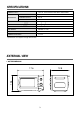
SPECIFICATIONS POWER SUPPLY MICROWAVE 120V AC, 60Hz SINGLE PHASE WITH GROUNDING INPUT POWER 950 W ENERGY OUTPUT 600 W FREQUENCY 2,450MHz OUTSIDE DIMENSIONS (W CAVITY DIMENSIONS (W H H D) D) 17.6 10.6 11.6 8.3 12.8 in 11.9 in CAVITY VOLUME 0.7 cu.ft NET WEIGHT APPROX. 21.0 lbs. TIMER 35min. DUAL SPEED POWER SELECTIONS 5 Levels * Specifications are subject to change without notice. EXTERNAL VIEW 1. OUTER DIMENSION 12.8 10.6 17.
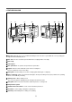
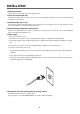
2. FEATURES DIAGRAM 1 2 8 3 7 6 4 9 5 0 q w r e 1 Door latch - When the door is closed, it will automatically shut off. If the door is opened while the oven is operating, the magnetron will automatically shut off. 2 Door seal - The door seal surfaces prevent microwaves escaping from the oven cavity. 3 Oven cavity 4 Control panel 5 Door open button - To open the door push the door open button. 6 Coupler- This fits over the shaft in the center of the oven cavity floor.
INSTALLATION 1. Steady, flat location. This microwave oven should be set on a steady, flat surface. 2. Leave space behind and side. All air vents should be kept a clearance. If all vents are covered during operation, the oven may be overheated and, eventually, cause oven failure. 3. Away from radio, and TV sets Poor television reception and radio interference may result if the oven is located close to a TV, radio, antenna, or feeder and so on. Position the oven as far from them as possible. 4.
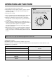
OPERATIONS AND FUNCTIONS 1. Connect the mains lead to an electrical outlet. 2. After placing the food in a suitable container, open the oven door and put it on the glass tray. The glass tray must always be in place during cooking. 3. Close the door securely. NOTE When setting timer for less than 10 minutes, turn the timer past 10 minutes and then return to the correct timer setting. 4. Choose cooking power level by setting V.P.C knob to the desired position. Refer to cookbook for recommended power levels.
DISASSEMBLY AND ASSEMBLY Cautions to be observed when troubleshooting. Unlike many other appliances, the microwave oven is high-voltage, high-current equipment. It is completely safety during normal operation. However, carelessness in servicing the oven can result in an electric shock or possible danger from a short circuit. You are asked to observe the following precautions carefully. 1. Always remove the power plug from the outlet before servicing. 2.
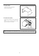
1. To remove cabinet 1) Remove four screws on cabinet back. 2) Pull the cabinet backward. 2. To remove door assembly 1) Remove two screws which secure the stopper hinge top. 2) Remove the door assembly from top plate of cavity. 3) Reverse the above for reassembly. NOTE : After replacing the door assembly, perform a check of correct alignment with the hinge and cavity front plate.
3. To remove door parts. REF NO. PART CODE PART NAME DESCRIPTION A01 3512210110 FRAME DOOR HIPS SG-970, HG-1760H 1 A02 3517007300 BARRIER-SCREEN *O PET T 0.125 1 A03 3515204120 STOPPER HINGE *T AS KOR-6L0B1A 1 A04 3511706130 DOOR PAINTING AS KOR-6L0B1A 1 A05 3517003700 BARRIER-SCREEN *I POLYESTER T 0.1 1 A06 3512302700 GASKET DOOR PP 1 A07 3513100700 HOOK POM 1 A08 3515101300 SPRING HOOK PW1 1 (1) Remove the gasket door from the door painting assembly.
4. Method to reduce the gap between the door seal and the oven front surface. (1) To reduce gap located on part ‘A’ • Loosen two screws on the stopper hinge top, and then push the door to contact the door seal to the oven front surface. • Tighten two screws. (2) To reduce gap located on part ‘B’ • Loosen two screws on the stopper hinge under, and then push the door to contact the door seal to the oven front surface. • Tighten two screws.
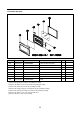
5. To remove control panel parts. REF NO. PART CODE PART NAME DESCRIPTION Q’TY B01 3513409500 KNOB VPC ABS SG-0760D, SG-175 1 B02 3516735040 CONTROL PANEL ABS VT-0826, AF-348 1 B03 3517402900 COUPLER VPC KNOB POM 1 B04 7122401211 SCREW TAPPING T2S TRS 4X12 MFZN 1 B05 7122401211 SCREW TAPPING T2S TRS 4X12 MFZN 2 B06 3518206440 TIMER VTCB35MFH0 1 B07 3513409400 KNOB ABS SG-0760D, SG-175 1 B08 3513702700 LEVER DOOR OPEN PP 1 B09 441G430171 SPRING BUTTON SWP DIA.
6. To remove high voltage capacitor. 1) Remove the screw which secure the grounding ring terminal of the H.V. diode and the capacitor holder. 2) Remove the H.V. diode from the capacitor holder. 3) Reverse the above steps for reassembly. ◆ High voltage circuit wiring 7. To remove magnetron. 1) Remove three screws which secure the magnetron. 2) Remove the magnetron. 3) Reverse the above steps for reassembly.
8. To remove wind guide assembly. 1) Remove the screw for earthing. 2) Remove the noise filter from the wind guide. 3) Remove the screw which secure the wind guide assembly. 4) Draw forward the wind guide assembly. 5) Pull the fan from the motor shaft. 6) Remove two screws which secure the motor shaded pole. 7) Remove the motor shaded pole. 8) Reverse the above steps for reassembly. 9. To remove H.V.transformer. 1) Remove four screws holding the H.V.transformer. 2) Remove the H.V.transformer.
INTERLOCK MECHANISM AND ADJUSTMENT The door lock mechanism is a device which has been specially designed to completely eliminate microwave radiation when the door is opened during operation, and thus to perfectly prevent the danger resulting from the leakage of microwave. CONDITION : DOOR CLOSED CONDITION : DOOR OPEN (1) Primary interlock switch When the door is closed, the hook locks the oven door. If the door is not closed properly, the oven will not operate.
TROUBLESHOOTING GUIDE Following the procedure below to check if the oven is defective or not. 1. Check grounding before trouble checking. 2. Be careful of the high voltage circuit. 3. Discharge the high voltage capacitor. 4. When checking the continuity of the switches, fuse or high voltage transformer, disconnect one lead wire from these parts and check continuity with the AC plug removed. To do otherwise may result in a false reading or damage to your meter.
Does the fan motor work when you shut the door and turn the timer? YES Does the oven lamp light? Does the turntable turn? NO Replace or repair oven lamp, turntable motor. YES Normal reading should be approx. 0 If microwave do not oscillate, check continuity of filament of magnetron. NO Continuity Check continuity filament tap (3.3V) of high voltage. No Continuity Replace high Voltage transformer Continuity Poor continuity Check continuity filament tap (3.3V) of high voltage.
MEASUREMENT AND TEST 1. MEASUREMENT OF THE MICROWAVE POWER OUTPUT Microwave output power can be checked by indirectly measuring the temperature rise of a certain amount of water exposed to the microwave as directed below. PROCEDURE 1. Microwave power output measurement is made with the microwave oven supplied at rated voltage and operated at its maximum microwave power setting with a load of 1000 5cc of potable water. 2.
2. MICROWAVE RADIATION TEST CAUTION : 1. Make sure to check the microwave leakage before and after repair of adjustment. 2. Always start measuring of an unknown field to assure safety for operating personnel from microwave energy. 3. Do not place your hands into any suspected microwave radiation field unless the safe density level is known. 4. Care should be taken not to place the eyes in direct line with the source of microwave energy. 5.
3. COMPONENT TEST PROCEDURE High voltage is present at the high voltage terminal of the high voltage transformer during any cooking cycle. It is neither necessary nor advisable to attempt measurement of the high voltage. Before touching any oven components or wiring, always unplug the oven from its power source and discharge the capacitor. 1. High voltage transformer (1) Remove connections from the transformer terminals and check continuity. (2) Normal readings should be as follows: Secondary winding .....
S/N : 3513509590 WIRING DIAGRAM 21
EXPLODED VIEW AND PARTS LIST 1. DOOR ASSEMBLY Refer to Disassembly and assembly. 2. CONTROL PANEL ASSEMBLY Refer to Disassembly and assembly. 3.
REF NO.
DAEWOO ELECTRONICS CORP. 686, AHYEON-DONG MAPO-GU SEOUL, KOREA C.P.O. BOX 8003 SEOUL, KOREA TELEX: DWELEC K28177-8 CABLE: “DAEWOOELEC” S/M NO. : OR6L051001 PRINTED DATE: Mar.