S/M No. : R8CBB5W001 Service Manual Microwave Oven Model: KOR-8CBB5W ✔ Caution : In this Manual, some parts can be changed for improving, their performance without notice in the parts list. So, if you need the latest parts information, please refer to PPL(Parts Price List) in Service Information Center (http://svc.dwe.co.kr). Mar.
PRECAUTIONS TO BE OBSERVED BEFORE AND DURING SERVICING TO AVOID POSSIBLE EXPOSURE TO EXCESSIVE MICROWAVE ENERGY (a) Do not operate or allow the oven to be operated with the door open.
SAFETY AND PRECAUTIONS 1. FOR SAFE OPERATION Damage that allows the microwave energy (that cooks or heats the food) to escape will result in poor cooking and may cause serious bodily injury to the operator. IF ANY OF THE FOLLOWING CONDITIONS EXIST, OPERATOR MUST NOT USE THE APPLIANCE. (Only a trained service personnel should make repairs.) (1) A broken door hinge. (2) A broken door viewing screen. (3) A broken front panel, oven cavity. (4) A loosened door lock. (5) A broken door lock.
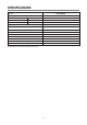
SPECIFICATIONS MODEL KOR-8CBB5W POWER SUPPLY 230V-50Hz, SINGLE PHASE WITH EARTHING MICROWAVE POWER CONSUMPTION 1200W GRILL COMBINATION MICROWAVE ENERGY OUTPUT 800W MICROWAVE FREQUENCY 2450MHz OUTSIDE DIMENSIONS (W X H X D) 465 x 287 x 364 mm CAVITY DIMENSIONS (W X H X D) 298 x 230 x 330 mm NET WEIGHT APPROX. 11.8 kg TIMER 59 min. 90 sec. function selections MICROWAVE POWER selections 10 LEVELS cavity volume 23 L * Specifications are subject to change without notice.
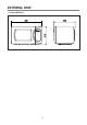
EXTERNAL VIEW 1.
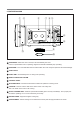
2. FEATURE DIAGRAM 1 2 3 7 45 6 8 9 q 0 1 DOOR HOOK - When the door is closed, it will automatically lock shut. If door is opened while oven is operating, magnetron tube will immediately stop operating. 2 DOOR SEAL - Door seal maintains the microwave within the oven cavity and prevents microwave leakage. 3 OVEN CAVITY 4 OVEN LAMP - Automatically turns on during oven operating. 5 SAFETY INTERLOCK SYSTEM 6 CONTROL PANEL 7 SPATTER SHIELD - Protects the microwave outlet from splashes of cooking foods.
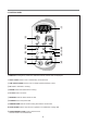
3. CONTROL PANEL 1 2 3 6 8 7 5 4 9 0 q 1 DISPLAY-Cooking time, power level, indicators and the current time are displayed. 2 AUTO COOK-Used to cook or reheat many of favorite food. 3 ONE TOUCH COOK-Used to cook or reheat specific quantities of food. 4 UP-Used to add time to cooking. 5 DOWN-Used to decrease time to cooking. 6 CLOCK-Used to set clock. 7 DEFROST-Used to defrost foods for time. 8 POWER-Used to set power level. 9 TIME SET PAD-Used to set the cooking time and the current time.
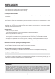
INSTALLATION 1. Steady, flat location This microwave oven should be set on a steady, flat surface. This microwave oven is designed for counter top use only. 2. Leave space behind and side All air vents should be kept a clearance. If all vents are covered during operation, the oven may overheat and, eventually, cause failure. 3. Away from radio, and TV sets Poor television reception and radio interference may result if the oven is located close to a TV, radio, antenna, or feeder and so on.
OPERATIONS AND FUNCTIONS 1. Connect the mains lead to an electrical outlet. 2. After placing the food in a suitable container, open the oven door and put it on the glass tray. The glass tray must always be in place during cooking. 3. Close the door securely. 4. When the oven door is opened, the light turns off. 5. The oven door can be opened at any time during operation by pushing the door release button on the control panel. The oven will automatically shut off.
DISASSEMBLY AND ASSEMBLY Cautions to be observed when troubleshooting. Unlike many other appliances, the microwave oven is high-voltage, high-current equipment. It is completely safe during normal operation. However, carelessness in servicing the oven can result in an electric shock or possible danger from a short circuit. You are asked to observe the following precautions carefully. 1. Always remove the power plug from the outlet before servicing. 2.
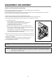
1. To remove cabinet 1) Remove three screws on cabinet back. 2) Pull the cabinet backward. 2. To remove door assembly 1) Remove two screws which secure the stopper hinge top. 2) Remove the door assembly from top plate of cavity. 3) Reverse the above for reassembly. NOTE : After replacing the door assembly, perform a check of correct alignment with the hinge and cavity front plate.
3. To remove door parts. DOOR ASSEMBLY : 3511730310 REF NO. PART CODE A01 3512209070 A02 PART NAME DESCRIPTION Q’TY FRAME DOOR HIPS SG-970 HG-1760H 1 3517007300 BARRIER-SCREEN*0 PET T0.125 1 A03 3515204100 STOPPER HINGE *T AS KOR-63150S 1 A04 3511719500 DOOR PAINTING AS KOR-6C0B5S 1 A05 3517002800 BARRIER-SCREEN *I POLYESTER T0.
4. Method to reduce the gap between the door seal and the oven front surface. (1) To reduce gap located on part ‘A’ Loosen two screws on stopper hinge top, and then push the door to contact the door seal to oven front surface. Tighten two screws. (2) To reduce gap located on part ‘B’ Loosen two screws on stopper hinge under, and then push the door to contact the door seal to oven front surface. Tighten two screws. NOTE : A small gap may be acceptable if the microwave leakage does not exceed 4mW/cm2.
5. To remove control panel parts. C/PANEL ASSEMBLY : PKCPSWF620 REF NO. PART CODE PART NAME DESCRIPTION Q’TY B01 3518571630 SWITCH MEMBRANE KOR-6QBB5S 1 B02 3516733830 CONTROL PANEL HIPS SG-970 HG-1760H 1 B03 PKMPMSBA60 PCB AS 6N(800W,W,10,59) 1 B04 7122401211 SCREW TAPPING T2S TRS 4X12 MFZN 4 REMARK (1) Remove the screw which secure the control panel, push up two snap fits and draw forward the control panel assembly.
6. To remove high voltage capacitor. 1) Remove a screw which secure the grounding ring terminal of the H.V. diode and the capacitor holder. 2) Remove the H.V. diode from the capacitor holder. 3) Reverse the above steps for reassembly. ◆ High voltage circuit wiring 7. To remove magnetron. 1) Remove a screw which secure the magnetron. 2) Remove the magnetron. 3) Reverse the above steps for reassembly.
8. To remove wind guide assembly. 1) Remove a screw for earthing. 2) Remove the noise filter from the wind guide. 3) Remove a screw which secure the wind guide assembly. 4) Draw forward the wind guide assembly. 5) Pull the fan from the motor shaft. 6) Remove two screws which secure the motor shaded pole. 7) Remove the motor shaded pole. 8) Reverse the above steps for reassembly. 9. To remove H.V.transformer. 1) Remove four screws holding the H.V.transformer. 2) Remove the H.V.transformer.
INTERLOCK MECHANISM AND ADJUSTMENT The door lock mechanism is a device which has been specially designed to completely eliminate microwave radiation when the door is opened during operation, and thus to perfectly prevent the danger resulting from the leakage of microwave. (1) Primary interlock switch When the door is closed, the hook locks the oven door. If the door is not closed properly, the oven will not operate. When the door is closed, the hook pushes the button of the microswitch.
TROUBLESHOOTING GUIDE Following the procedure below to check if the oven is defective or not. 1. Check grounding before trouble checking. 2. Be careful of the high voltage circuit. 3. Discharge the high voltage capacitor. 4. When checking the continuity of the switches, fuse or high voltage transformer, disconnect one lead wire from these parts and check continuity with the AC plug removed. To do otherwise may result in a false reading or damage to your meter.
CONDITION Outlet has proper voltage Fuse does not blow. CHECK RESULT CAUSE REMEDY No Continuity Defective magnetron Replace Check continuity of magnetron Check continuity of noise filter board No Continuity Defective magnetron Replace Check continuity of power supply cord No Continuity Open power supply cord Replace Normal Defective touch control circuit Replace NOTE All these switches must be replaced at the same time, please refer to “Interlock Mechanism And Adjustment”.
(TROUBLE 3) No microwave oscillation even though fan motor rotates.
(TROUBLE 4) The following visual conditions indicate a probable defective touch control circuit 1. Incomplete segments, 1) Segments missing. 2) Partical segments missing. 3) Digit flickering other than normal display slight flickering. 4) " :0" does not display when power is on. 2. A distinct change in the display are not on when they numbers is the display. 3. One or more digits in the display are not on when they should be. 4. Display indicates a number different from one touched. 5.
MEASUREMENT AND TEST 1. MEASUREMENT OF THE MICROWAVE POWER OUTPUT Microwave output power can be checked by indirectly measuring the temperature rise of a certain amount of water exposed to the microwave as directed below. PROCEDURE 1. Microwave power output measurement is made with the microwave oven supplied at rated voltage and operated at its maximum microwave power setting with a load of 1000±5cc of potable water. 2.
2. MICROWAVE RADIATION TEST CAUTION : 1. Make sure to check the microwave leakage before and after repair of adjustment. 2. Always start measuring of an unknown field to assure safety for operating personnel from microwave energy. 3. Do not place your hands into any suspected microwave radiation field unless the safe density level is known. 4. Care should be taken not to place the eyes in direct line with the source of microwave energy. 5.
3. COMPONENT TEST PROCEDURE • High voltage is present at the high voltage terminal of the high voltage transformer during any cooking cycle. • It is neither necessary nor advisable to attempt measurement of the high voltage. • Before touching any oven components or wiring, always unplug the oven from its power source and discharge the capacitor. 1. High voltage transformer (1) Remove connections from the transformer terminals and check continuity.
WIRING DIAGRAM 24
PRINTED CIRCUIT BOARD 1. CIRCUIT CHECK PROCEDURE 1. Low Voltage Transformer check The low voltage transformer is located on the P.C.B. Measuring condition: input voltage : 230V/Frequency : 50Hz Terminal Voltage 5-6-7 LOAD AC 12.6 V NO LOAD AC 14.7 V NOTE : 1. Refer to Circuit Diagram (point 4). 2. Secondary side voltage of the low voltage transformer changes in proportion to fluctuation of power source voltage. 3. The allowable tolerance of the secondary voltage is within 5% of nominal voltage. 2.
MP1 MP2 GND Measure Point 26
3. When there is no microwave oscillation 1) When touching START pad, oven lamp does not turn on. Fan motor does not rotate, but cook indicator in display comes on. B A RY2 42 D10 (TRAY LAMP) Q10 RY2 - Check method POINT A B RELAY 2 ON 5VDC GND RELAY 2 OFF GND 12VDC STATE 2) When touching START pad, oven lamp turns on. Fan motor and turntable rotate and cook indicator in display comes on.
2.
3. PCB LOCATION NO.
EXPLODED VIEW AND PARTS LIST 1. DOOR ASSEMBLY Refer to Disassembly and assembly. 2. CONTROL PANEL ASSEMBLY Refer to Disassembly and assembly. 3.
✔ Caution : In this Manual, some parts can be changed for improving, their performance without notice in the parts list. So, if you need the latest parts information, please refer to PPL(Parts Price List) in Service Information Center (http://svc.dwe.co.kr).
DAEWOO ELECTRONICS CORP. 1-2, Jeo-dong 1(il)-ga, Jung-gu, Seoul, Korea C.P.O. BOX 8003 SEOUL, KOREA TELEX: DWELEC K28177-8 CABLE: “DAEWOOELEC” S/M NO. : PRINTED DATE: Mar.
ABOUT THIS MANUAL vision@creativeL@incN Էܞ ړĸ ࣃۉʷ V Ѩێ ݖΟӂ˱ T ࠚ ɽ ʁ Ũٙ ݘɮ m@o@d@e@l korMXcbbUw@HsOmI ܂ RPQPNPSNQP ր Q R ۑ ܄ S T U ܆ ࣽ Ŕ ÿ ې ॥ լ memo@@߭ SS QPNPSNQPMहݖL@ह˒ݖL@SL@QQL@QSL@RYL@SPL@SQ@֭Ŕ X QPNPSNQQMS@ր֭@܄Ŕ XQ ِ͊ߏ vision ɽ ʁ і О ր telZ WSPMPVVP@faxZ WSPMSWXX